Turn off automatic portrait and landscape alignment in the camera. This will no longer change the so-called main point position and you will get better accuracy.
Switch off the automatic camera shake correction in the camera. This prevents an exact calibration of the camera during the calculation or the correct application of the calibration data if the camera is already calibrated.
It is best to use fixed focal length lenses. These are always faster than zoom lenses and will give you better images, especially in low light conditions.
If you use zoom lenses: Set the lens to either full stop wide angle, or full stop zoom and do not change this zoom setting anymore if possible. The full wide angle setting is normally always good to use.
Before taking pictures
Set the aperture, exposure, and ISO number correctly: The aperture should be as high as possible so that you have well-lit, sharp and noise-free pictures, with freehand photography the exposure time should not be longer than 1/60s, otherwise the pictures can blur.
Focus once before taking the first picture and turn autofocus off. This allows all images to be calculated with the same mathematical camera model and improves accuracy.
While taking pictures
Do not zoom or focus: this will allow all images to be calculated with the same camera model, otherwise ELCOVISION 10 will have to calibrate each image separately, which will reduce accuracy.
Never take 2 pictures from exactly the same position.Always take at least half a step to the side between 2 images: images from the same point of view cannot produce exact points because of the flat ray intersection.
Photograph the object with 75% overlap between 2 images: With a flight planning software for drones it is best to set a 75% overlap between the images and a 60% - 75% overlap of the stripes.
If possible, photograph especially large objects in 2 passes: The first time you take a picture of it, the second time you take a picture of all the details you are interested in. This prevents you from accidentally forgetting parts of the object: If details are also photographed in the 1st pass, you will get bogged down and often have holes in the photo block.
Why must autofocus be disabled, or why is it not allowed to refocus during image acquisition?
During the automatic orientation process, ELCOVISION 10 calibrates several camera parameters, including:
The camera constant (focal length),
The principal point location, and
The parameters for radial and tangential distortion.
The most critical of these is the accurate determination of the camera constant (focal length) of the lens. ELCOVISION 10 typically computes this value with an accuracy of 0.005 mm or better.
If the camera focuses at different distances, either manually or via autofocus, the effective focal length changes depending on the focusing distance: Focusing on nearby objects increases the focal length, while focusing on distant objects shortens it. These changes can amount to several millimetres, which is several orders of magnitude bigger than the calibration accuracy.
When images from the same camera with varying focal lengths are used during automatic orientation but ELCOVISION 10 assumes a single focal length for all images, the result is a systematic error: The incorrect focal length values impose internal constraints on the photo block, significantly degrading the precision of the reconstructed points.
Individually calibrating each image is also not a viable solution, as this would eliminate the redundancy (over-determination) required for achieving high accuracy.
Although ELCOVISION 10 offers an autofocus compensation mechanism as part of the global orientation process, and this does improve the results significantly, the accuracy is still inferior to what can be achieved with autofocus disabled.
Exposure metering
All current digital cameras are equipped with very good automatic systems, which take excellent pictures under almost all lighting conditions. Nevertheless, you should have some basic knowledge about the correct exposure of images:
The selective metering (spot metering) measures the light conditions in the middle of the image area; the large field integral metering (multi spot metering) measures the light conditions in the whole image area.
Selective metering of the exposure makes sense if the area of an object that is of interest for evaluation has very different lighting conditions to the surroundings.
If there are not too great differences in the illumination conditions in a certain situation and if the entire situation is of interest for the evaluation, the integral measurement must be used for the exposure measurement. Thus, the entire object area is imaged in the best possible way.
It is important to note that an overexposed image, i.e. an image that is too bright, can no longer be recovered. Image areas that are overlit are irrevocably lost, no image information can be restored:
OverexposedOverexposure maximal corrected
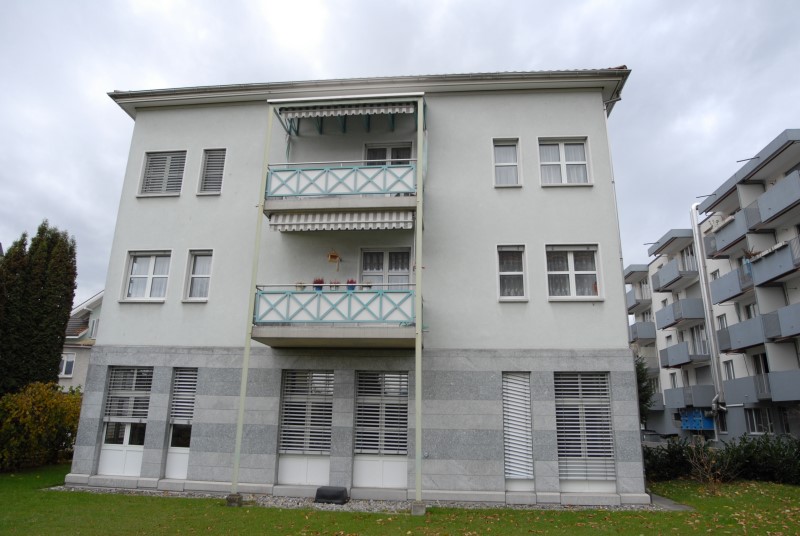
From an underexposed, too dark image, a lot of information can still be gained by simple brightening or gamma correction, it can be almost completely corrected and used normally:
UnderexposedUnderexposure corrected
With automatic orientation, ELCOVISION 10 automatically applies various correction methods to orientate the images anyway. Therefore, slightly underexposed images work well, while overexposed images can cause problems.
Aperture selection
Since close-up photogrammetry normally works with fixed lenses or lenses focused at certain distances, the sharpness of the image must be achieved by selecting the aperture. The aim is always to work with as small an aperture as possible. Optimal f-stops are normally in the range 5.6 - 11, if the f-number becomes larger, the exposure times become too large or the images too dark.
But beware: For freehand shots the exposure time should not be longer than one 1/60 second (danger of camera shake). When using a telephoto lens, the longest exposure time must be 1/125 second or less.
Lighting
Illumination by means of lamps always makes sense if cast shadows are to be expected or strong reflections from the object are to be expected. Reflections must be taken into account, especially in the case of factory buildings, pipelines, etc.
Drop shadows occur indoors or in highly structured objects. If lamps are used in such cases, shadows can be removed by moving the lamps.
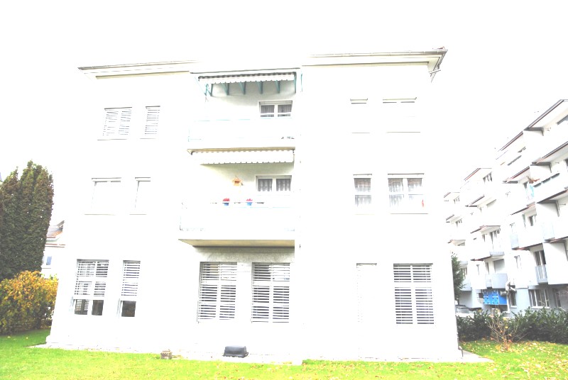
The best natural light in the open is when the sky is slightly overcast. In this case, there are no hard shadows and the entire object is usually uniformly illuminated.
Due to cloud cover soft light and no harsh shadowsBright sunshine makes for harsh shadows
Imaging set-ups for 3D photogrammetry
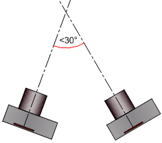
When shooting for automatic orientation, the convergence angle between 2 images should not exceed 30°, if the images are manually oriented, the convergence angle should be limited to 90°, so that points can still be easily recognized.
Points that are to be measured in three dimensions (X-, Y-, Z-coordinate) must be visible in at least 2, better 3 or 4, images from different points of view. This means approx. 75% image overlap or ideally more between 2 consecutive images.
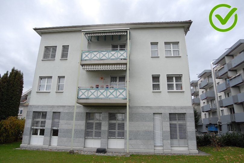
The photos should be taken as format-filling as possible, so that accuracy is not wasted over the image scale. Grass, trees or blue sky are of no interest in most cases.
Despite the considerations of accuracy, it often makes sense to approach the object closer than necessary. The recognizability of the object details is thereby considerably improved, the evaluation can be carried out much more detailed.
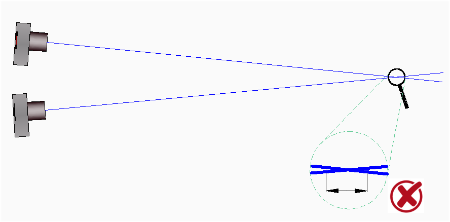
It is of utmost importance that the pictures are taken from different points of view! Pictures taken from almost the same point of view are unusable because of the resulting very flat beam intersection and lead to poor measurement accuracies!
A too flat, slanted ray intersection leads to poor measurement accuracy in the depth, i.e. in the direction of view, but the measurement accuracy parallel to the image planes is usually good:
Grinding ray intersection: Poor accuracy in the direction of view
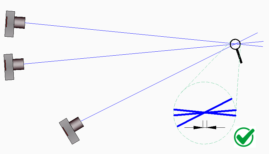
By taking a 3rd picture from a more distant viewpoint, the measuring accuracy of the object point is significantly increased:
Third measurement now gives good accuracy in all directions.
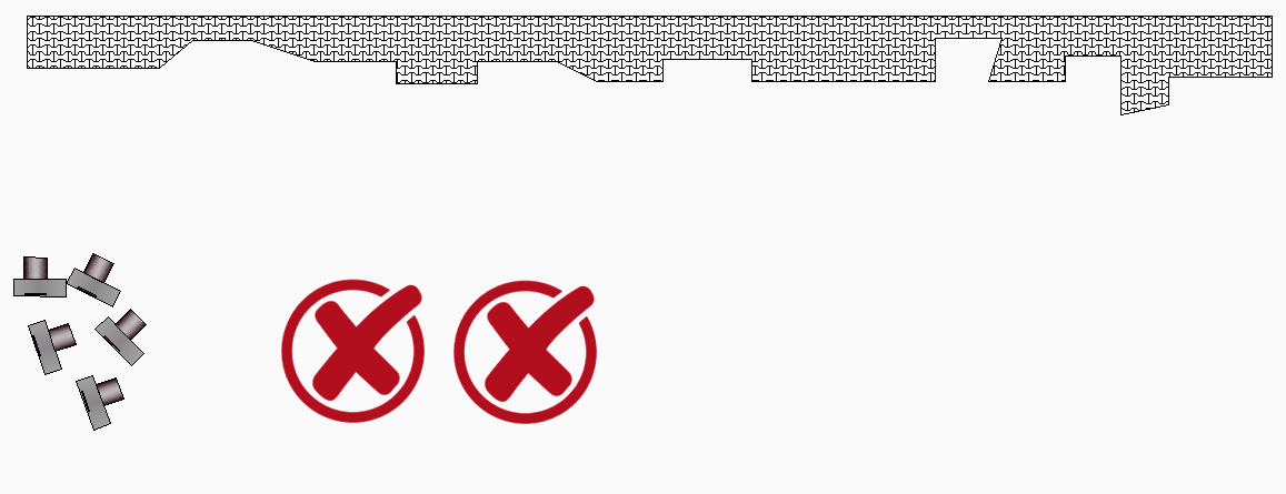
General Setups
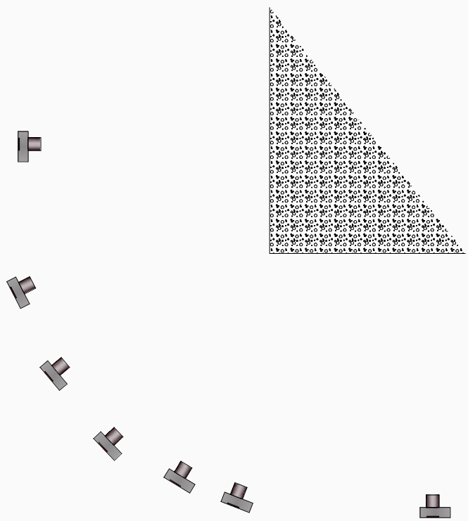
This is not the way to do it, the object is practically photographed from only one point of view, there are almost only glancing ray intersections:
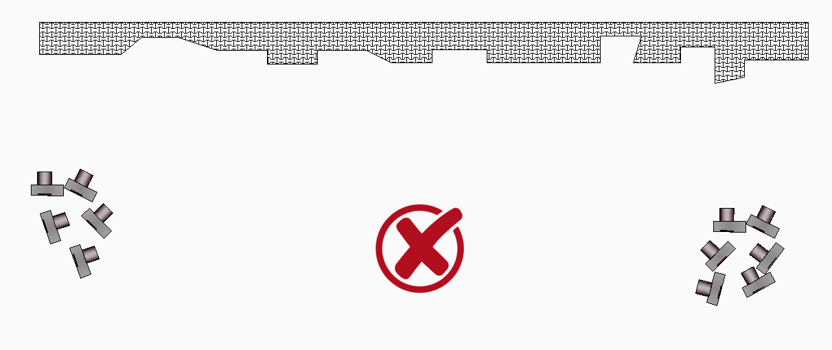
Somewhat better but still unusable is the following photographic setup, despite the more than 10 images, there are effectively only 2 viewpoints, which also suffer from glancing ray intersections.
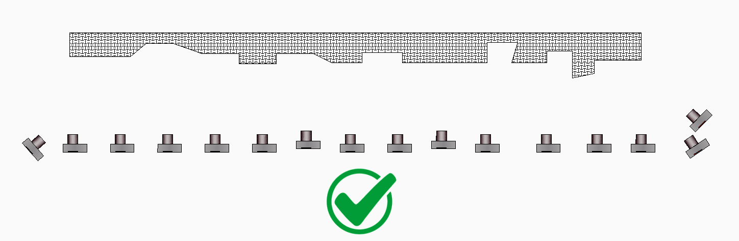
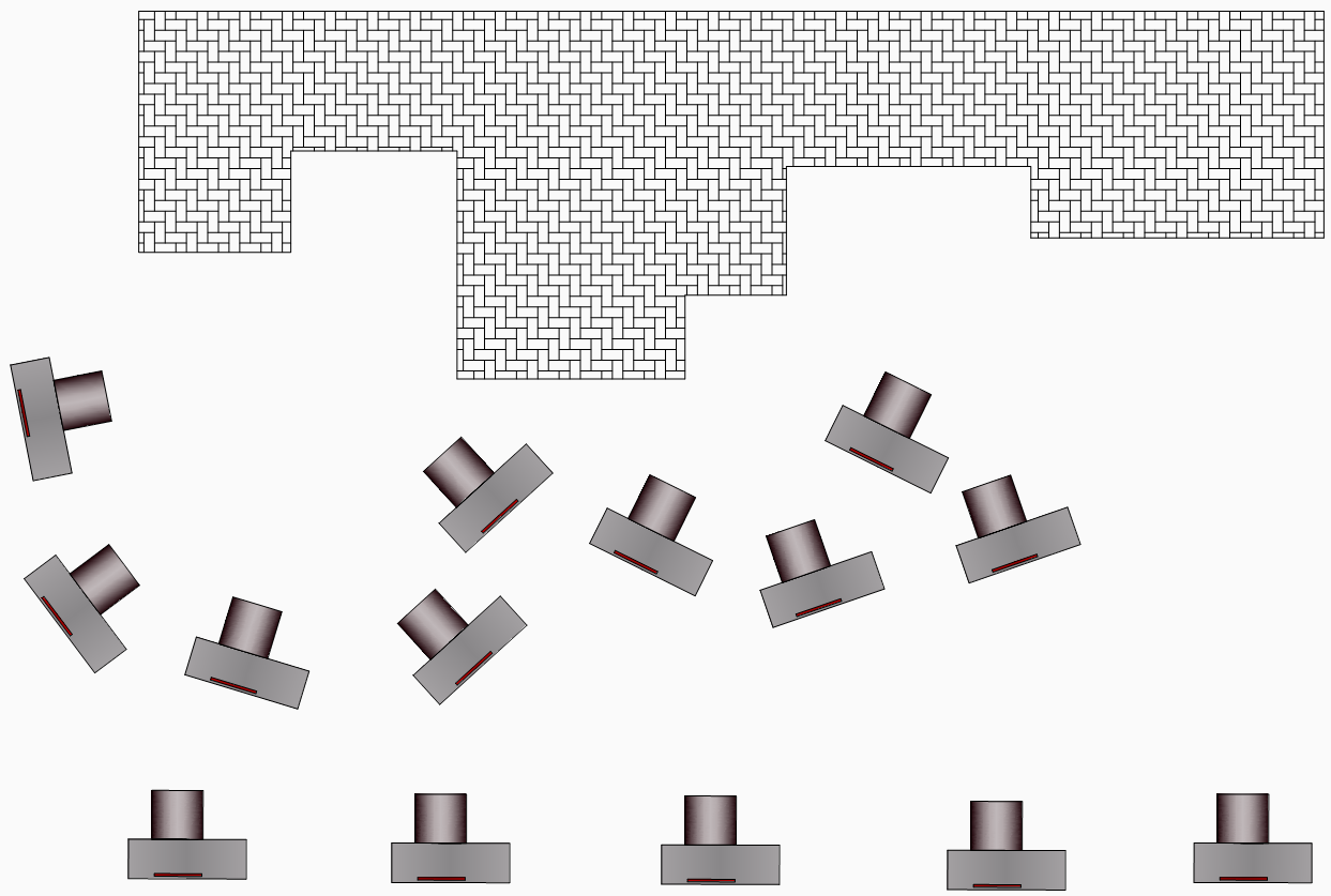
The following photographic setup is much better, the object is photographed over the whole area, the well separated viewpoints lead to good accuracies, as every point on the object is visible in many images due to the big image overlap:
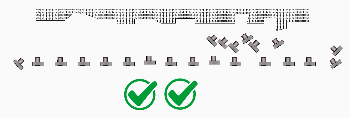
However, there may still be visual shadows in the indentations in which measurements cannot be taken, so additional images are taken in an even better imaging arrangement:
Here care is also taken to ensure that every point in the indentations is also visible in at least 3 images.
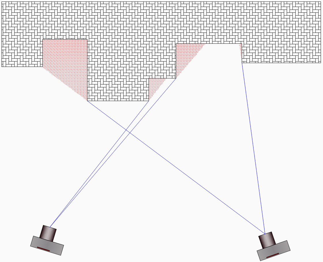
Capturing highly structured objects
Highly structured objects and large base distances often lead to visual shadows in which it is not possible to measure:
Red: Visibility shadows of the respective viewpoints
The solution here is either to go up in the air or better to cover the object completely with a more distant series of pictures and then additionally photograph the presumably hidden parts with 2-3 pictures each:
Shooting around an object corner
It is best to photograph around object corners with 4-5 images, thus keeping the maximum convergence angle of 30° for automatic orientation:
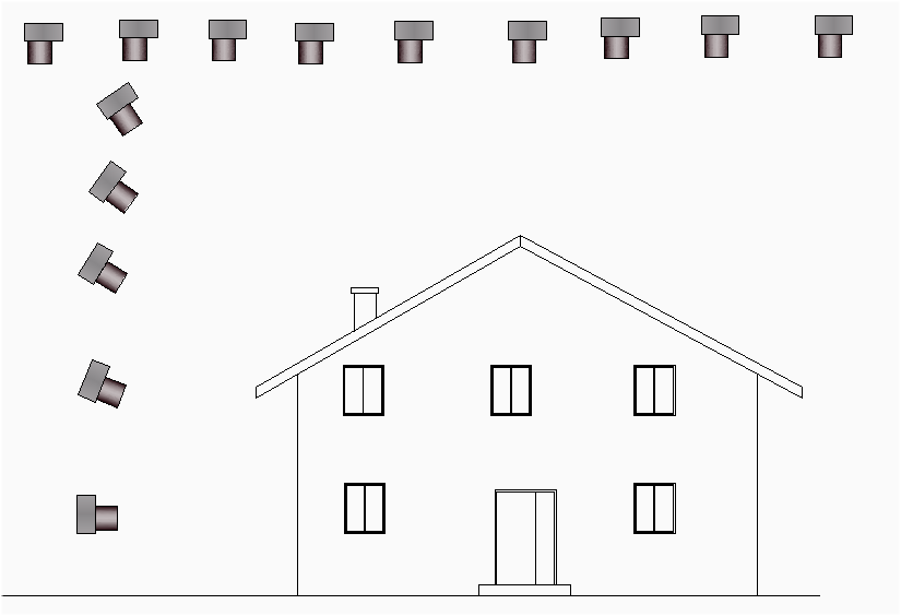
Photography of a small building or object
It is best to walk around the object and take a picture every 1-2 steps, details are best photographed with a 2nd pass:
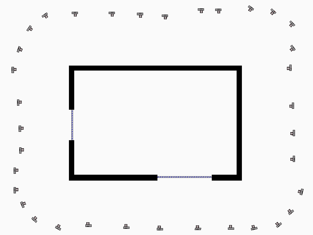
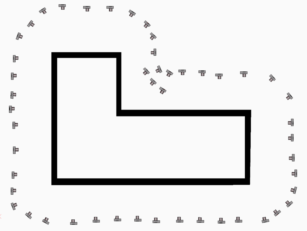
Building with inner courtyard
Photography of interiors
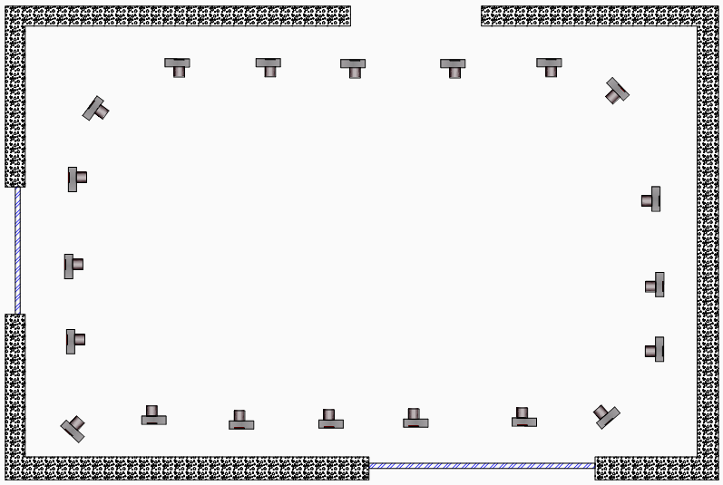
When taking pictures indoors, the arrangement of the pictures and also the number of pictures strongly depend on the interior design of the room. This is due to the concealment caused by pieces of furniture in the room. It is best to photograph the rooms with the back to the wall, the wider the angle of the lens the better:
and then afterwards furniture and visual shadows are covered as best as possible with additional pictures.
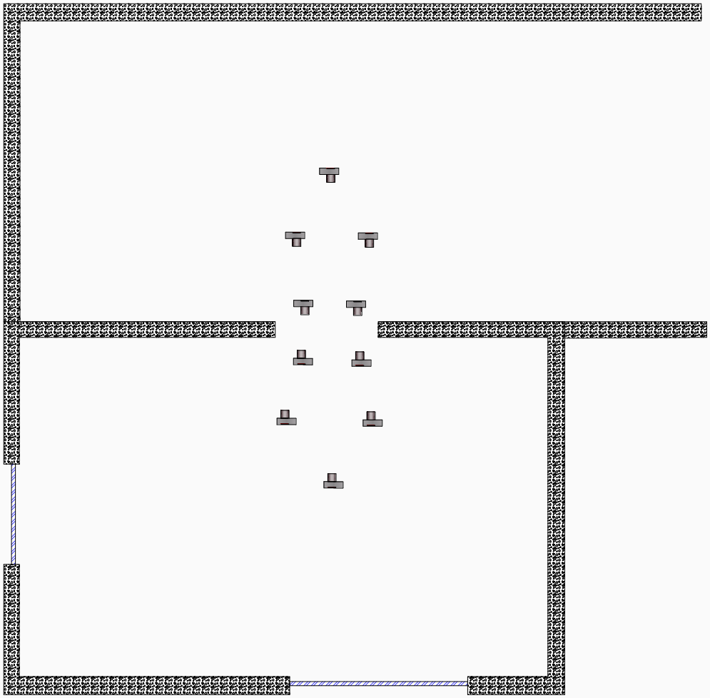
Passage to the next room
The best way to photograph through doors is with pictures taken in pairs; the walls opposite each other then provide the connection points:
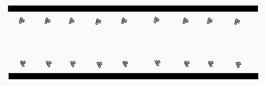
Recording of a long corridor
It is best to make pairs of stereo images that are aligned slightly to the opposite wall. If possible, the floor should be included as well, because often there are more points for the connection:
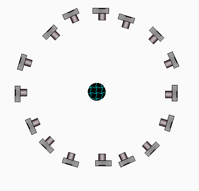
Photographing a Round Object
Round objects such as trees, columns, etc. can be photographed as follows:
Please note that the maximum convergence angle between two images is 30°, meaning the minimum number of images is 360°/30° = 12 images. To be on the safe side, you should take roughly twice that number of images.
Aerial surveys: With drones, aircraft, helicopters ...
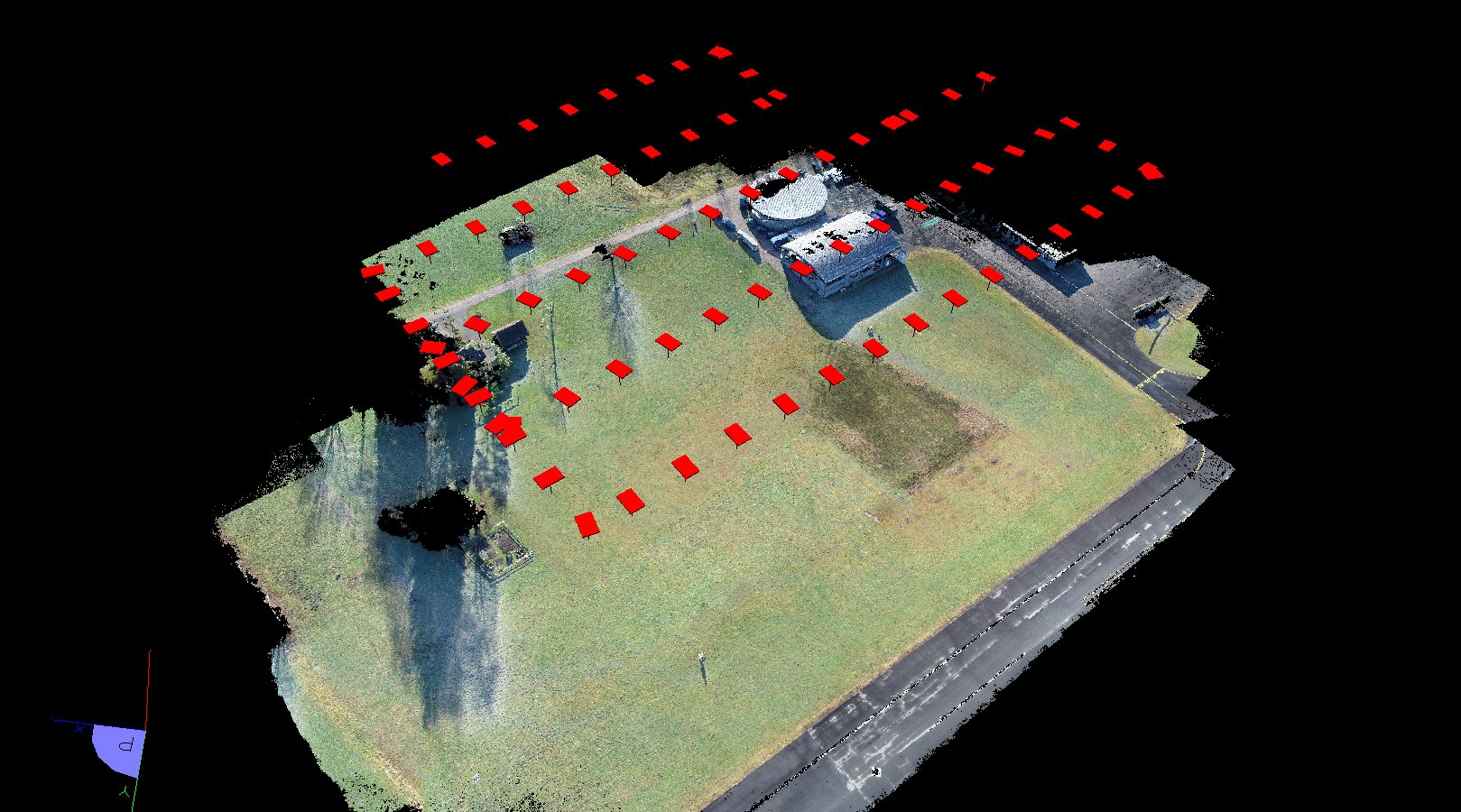
The object should be flown in strips, the images and strips should overlap by 75%. This way every point on the ground will be visible in about 6 images: The orientation of the image formation will be very stable and a very good high-density point cloud can be calculated, where any point on the object should be visible in 4 or more images.
Furthermore, special attention should be paid to the fact that drones and aeroplanes, helicopters etc. continue to move during the recording, i.e. the camera also continues to move. Here is a table that shows how far a camera moves while taking a picture at different flight speeds and exposure times:
Flight_speed_______
1/60s
1/100s
1/125s
1/250s
1/500s
1/1000s
3,6 km/h = 1 m/s
1,67cm
1,00cm
0,80cm
0,40cm
0,20cm
0,10cm
7,2 km/h = 2 m/s
3,33cm
2,00cm
1,60cm
0,80cm
0,40cm
0,20cm
10,8 km/h = 3 m/s
5,00cm
3,00cm
2,40cm
1,20cm
0,60cm
0,30cm
14,4 km/h = 4 m/s
6,67cm
4,00cm
3,20cm
1,60cm
0,80cm
0,40cm
18,0 km/h = 5 m/s
8,33cm
5,00cm
4,00cm
2,00cm
1,00cm
0,50cm
21,6 km/h = 6 m/s
10,00cm
6,00cm
4,80cm
2,40cm
1,20cm
0,60cm
25,2 km/h = 7 m/s
11,67cm
7,00cm
5,60cm
2,80cm
1,40cm
0,70cm
28,8 km/h = 8 m/s
13,33cm
8,00cm
6,40cm
3,20cm
1,60cm
0,80cm
32,4 km/h = 9 m/s
15,00cm
9,00cm
7,20cm
3,60cm
1,80cm
0,90cm
36,0 km/h = 10 m/s
16,67cm
10,00cm
8,00cm
4,00cm
2,00cm
1,00cm
54,0 km/h = 15 m/s
25,00cm
15,00cm
12,00cm
6,00cm
3,00cm
1,50cm
72,0 km/h = 20 m/s
33,33cm
20,00cm
16,00cm
8,00cm
4,00cm
2,00cm
As a result, the sensor size (CCD size) can no longer be assumed to be invariable. The sensor becomes "longer" in the direction of flight. The camera calibration, which is based on the assumption that the sensor size is invariable, becomes significantly worse and poorer accuracies are achieved as a result. This effect can be minimised by flying as slowly as possible, setting the exposure time as short as possible and flying as high as possible. At altitudes of about 30m, for example, you should not fly faster than 2m/s and set exposure times shorter than 1/500s.
It is also best to use an ISO sensitivity of 400 or higher so that the shortest possible exposure time can be set.
PMS AG provides an Excel table that can be used to determine the maximum speed that can be flown at a given altitude, camera and exposure time so that this deterioration in accuracy can be minimised or neglected.
Linking drone and terrestrial images
If one wants to use drone images with images from normal cameras in a joint project, the maximum permissible convergence angle of 30° must be respected. The solution here is simply to ascend or descend with the drone and pan the camera along: If a larger area is flown over, this should be done several times at different points so that there is a good link between the drone images and the terrestrial images.
Measurement accuracy
Overview
Photogrammetry differs fundamentally from other measuring methods when the achievable accuracies are considered: In principle, one can achieve any desired accuracy with corresponding effort.
Or viewed the other way around: If you know which accuracy you need, you have to keep a maximum shooting distance with a given camera/lens combination to achieve this accuracy, or with a given shooting distance, what focal length the lens and/or what resolution the camera must have to achieve this accuracy.
Rules of the thumb
The accuracy you achieve with ELCOVISION 10 is at natural points about the pixel size of the object.
If points are signaled with ELCOVISION 10 targets, an accuracy in the range of 0.1 - 0.01*[pixel size at object] is normally achieved at these points, i.e. approx. 10 to 100 times more accurate than at natural points.
The higher the quality of the camera-lens combination, the better the images, the better the accuracy.
Fixed focal length lenses are faster than zoom lenses. With the same lighting conditions, the f-number can therefore be increased, the images become sharper and the accuracies better.
Do not zoom or refocus while taking pictures. If this is done, the corresponding images must be simultaneously calibrated by ELCOVISION 10 and the achievable accuracy may decrease.
If non-calibrated cameras are used, the accuracy will deteriorate by a factor of 1-4 depending on the camera and recording configuration.
Examples of Accuracy Estimates for Terrestrial Images
In the following, the example of an approx. 12m wide façade is used to demonstrate how the image scale or the pixel size on the object changes with the shooting distance and what effects this has on the achievable accuracy..
Too Much Surroundings in the Pictures
The façade is taken from very far away and/or with a wide-angle lens. You see a lot of surroundings and sky, which is usually not useful.
Camera Resolution
12 MPixel 4000*3000 Pixel
24 MPixel 6000*4000 Pixel
36 MPixel 7360 * 4912 Pixel
Facade in picture
~ 1200* 800 Pixel
~ 1800 * 1200 Pixel
~ 2200 * 1470 Pixel
Pixel size
~ 12m/1200 Pixel = 1cm/Pixel
~ 12m/1800 Pixel = 6mm/Pixel
~ 12m/2200 Pixel = 5mm/Pixel
Accuracy
~ 1cm*0.7 = 7mm
~ 6mm*0.7 = 4.2mm
~ 5mm*0.7 = 3.5mm
Frame Filling Shot
The façade is correctly photographed in full-frame, you can't see much of the surroundings..
Camera Resolution
12 MPixel 4000*3000 Pixel
24 MPixel 6000*4000 Pixel
36 MPixel 7360 * 4912 Pixel
Facade in picture
~ 3500 * 2330 Pixel
~ 5250* 3500 Pixel
~ 6440 * 4230 Pixel
Pixel size
~ 12m/3500 Pixel = 3.5mm/Pixel
~ 12m/ 5250 Pixel = 2.2mm/Pixel
~ 12m/6440 Pixel = 1.8mm/Pixel
Accuracy
~ 3.5mm*0.7 = 2.5mm
~ 2.2mm*0.7 = 1.5mm
~ 1.8mm*0.7 = 1.3mm
Detail Photos
Only a part of approx. 4*3m of the façade has been photographed.
Camera Resolution
12 MPixel 4000*3000 Pixel
24 MPixel 6000*4000 Pixel
36 MPixel 7360 * 4912 Pixel
Pixel size
~ 4m/4000 Pixel = 1mm/Pixel
~ 4m/ 6000 Pixel = 0.6mm/Pixel
~ 4m/7360 Pixel = 0.5mm/Pixel
Accuracy
~ 1mm*0.7 = 0.7mm
~ 0.6mm*0.7 = 0.42mm
~ 0.5mm*0.7 =0.35mm
Reference distances for local coordinate systems
If a local coordinate system is to be used later, at least one reference distance must be measured on the object or in the vicinity. In order to be able to recognise possible errors such as wrong measurements, number errors when writing down the distance from ELCOVISION 10, at least 2 or better 3 reference distances should be measured.
Distance measurements with tape measure, DISTO, metre rule
The distances should be in the order of magnitude of the object so that no error extrapolation occurs.
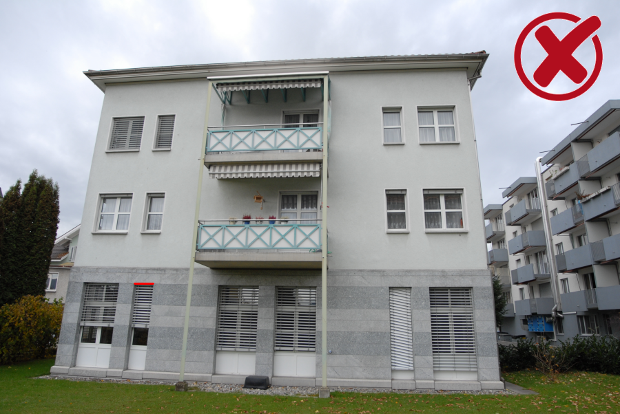
This is not how it should be done
Short reference distance approx. 0.5m at a window, facade approx. 12m wide. 1mm error in the reference distance extrapolates to 1mm*12/0.5 = 2.4cm on the width of the facade!
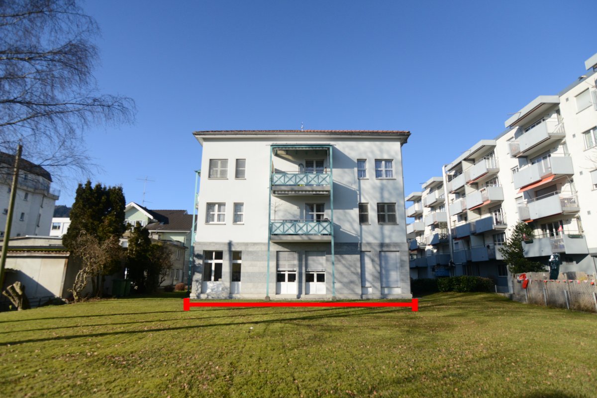
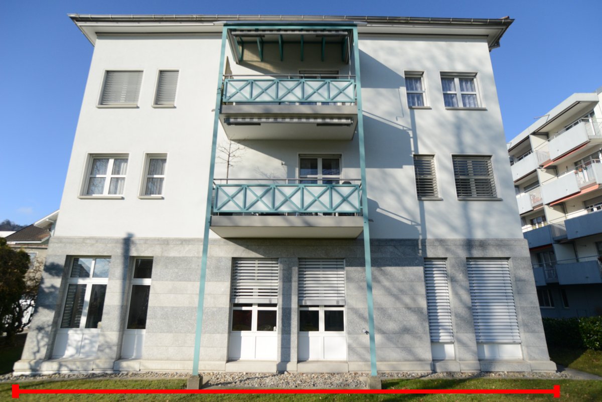
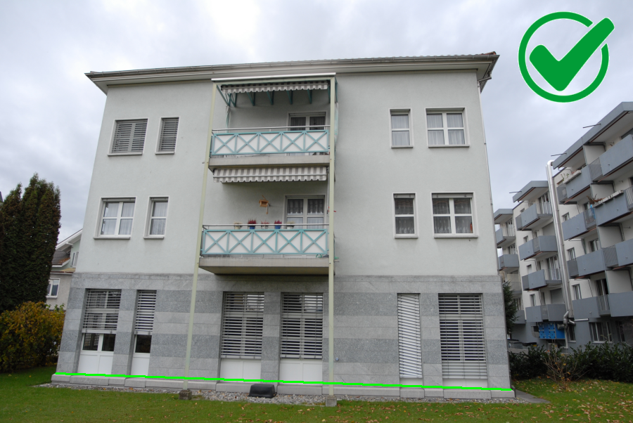
This is ideal
Reference distance over the entire width of the façade, thus no error extrapolation, the error even becomes smaller towards the inside:
Levelling staffs as reference sections
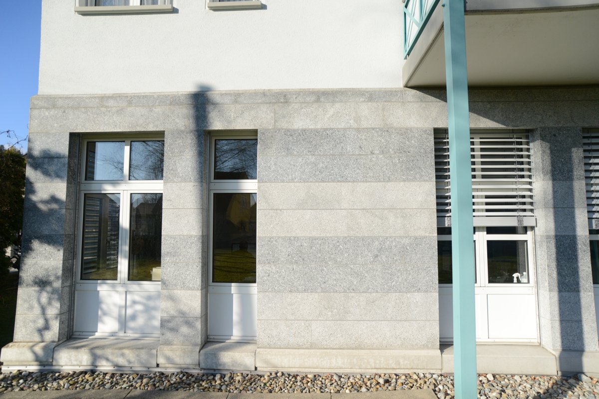
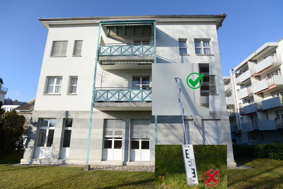
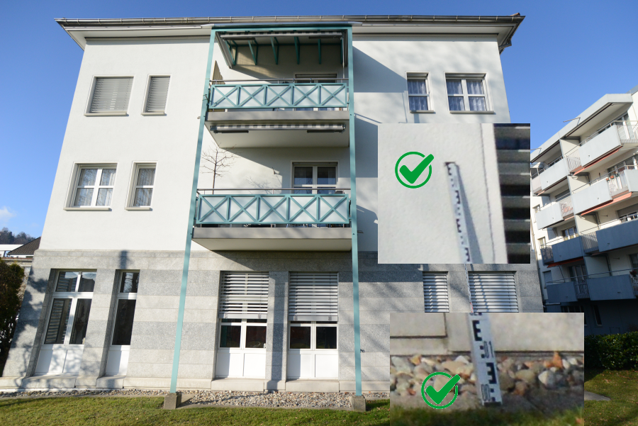
Levelling staffs are ideal reference lines for smaller objects such as single-family houses. Several staffs should also be used so that possible problems due to poor visibility can be avoided. The following is important:
Fully extend the Levelling staffs!
Pay attention to the visibility of both ends of the Levelling staffs!
Lower end of the levelling staff hidden by grassBoth ends of the levelling staff clearly visible
Precision in aerial photography e.g. Drone images
In the case of aerial photographs, a distinction is usually made between position accuracy and height accuracy. The reason for this is that you normally have mainly vertical shots and no oblique shots.
The position accuracy is identical to the pixel size of the object, and is mainly determined by the focal length and resolution of the camera.
For practical purposes, altitude accuracy depends almost exclusively on flight altitude. The camera resolution plays hardly a role here, provided it is a normal or high-quality camera, as a rule of thumb one has an altitude accuracy of approx. 0.003*flight altitude.
Here are some tables with the typical precision for cameras with different sensors for different focal lengths and flight altitudes, Position precision is in italic script
Full format Sensor: approx. 36*24mm; 24 MPixel: 6000*4000 Pixel
Altitude
Height prec.
8 mm Lens
15 mm Lens
20 mm Lens
30 mm Lens
10 m
0.3 cm
0.51 cm
0.27 cm
0.21 cm
0.14 cm
15 m
0.5 cm
0.77 cm
0.41 cm
0.31 cm
0.21 cm
20 m
0.7 cm
1.03 cm
0.55 cm
0.41 cm
0.27 cm
30 m
1.0 cm
1.54 cm
0.82 cm
0.62 cm
0.41 cm
40 m
1.3 cm
2.05 cm
1.09 cm
0.82 cm
0.55 cm
50 m
1.7 cm
2.56 cm
1.37 cm
1.03 cm
0.68 cm
60 m
2.0 cm
3.08 cm
1.64 cm
1.23 cm
0.82 cm
80 m
2.6 cm
4.10 cm
2.19 cm
1.64 cm
1.09 cm
100 m
3.3 cm
5.13 cm
2.73 cm
2.05 cm
1.37 cm
120 m
4.0 cm
6.15 cm
3.28 cm
2.46 cm
1.64 cm
Full format Sensor: approx. 36*24mm; 36MPixel: 7360*4900 Pixel
Altitude
Height prec.
8 mm Lens
15 mm Lens
20 mm Lens
30 mm Lens
10 m
0.3 cm
0.43 cm
0.23 cm
0.17 cm
0.11 cm
15 m
0.5 cm
0.64 cm
0.34 cm
0.26 cm
0.17 cm
20 m
0.7 cm
0.86 cm
0.46 cm
0.34 cm
0.23 cm
30 m
1.0 cm
1.28 cm
0.68 cm
0.51 cm
0.34 cm
40 m
1.3 cm
1.71 cm
0.91 cm
0.68 cm
0.46 cm
50 m
1.7 cm
2.14 cm
1.14 cm
0.86 cm
0.57 cm
60 m
2.0 cm
2.57 cm
1.37 cm
1.03 cm
0.68 cm
80 m
2.6 cm
3.42 cm
1.83 cm
1.37 cm
0.91 cm
100 m
3.3 cm
4.28 cm
2.28 cm
1.71 cm
1.14 cm
120 m
4.0 cm
5.14 cm
2.74 cm
2.05 cm
1.37 cm
Drones GPS Accuracies
Most drones are equipped with GPS. However, only drones with a so-called RTK GPS (Real Time Kinematic) are really suitable for surveying purposes: The positioning accuracy of conventional drone GPS is in the range of 1 to 10 metres and is therefore almost useless for surveying. RTK GPS, on the other hand, offer much higher precision, typically in the range of 1 to 10 centimetres. This is sufficient in many cases, but there are situations in which even this accuracy is not good enough. An simplified example will illustrate this:
2 drone positions with GPS accuracy R, not to scale
The GPS accuracy R would be 10 cm. The actual distance D between the two drone positions will be 20 metres. In the most unfavourable cases, the GPS distances can vary as follows::
In this case, the maximum scaling error is 2%. This means that a 10m long section in the area overflown can have a measurement error of up to ±10cm.
The following approaches can be used as a solution to this problem:
Fly over a significantly larger area: As GPS position errors are randomly distributed, they largely cancel each other out over a larger area and the scaling errors drop significantly, often to < 5mm over 10m
Do not use the GPS coordinates for small objects and instead use exact distances for scaling, as described in this example: Quick guide to drone roof surveying.
Use 5-8 control points that have been measured with a surveying GPS or a total station. These can then be used as control points for the transformation.
Photos or Videos?
Answer: Photos! You should not use videos if somehow possible!
Videos have the following disadvantages compared to photos:
Lower Resolution:
This automatically results in poorer accuracy because the pixel size on the object is bigger. See the discussion above on "Examples of accuracy estimates for terrestrial images".
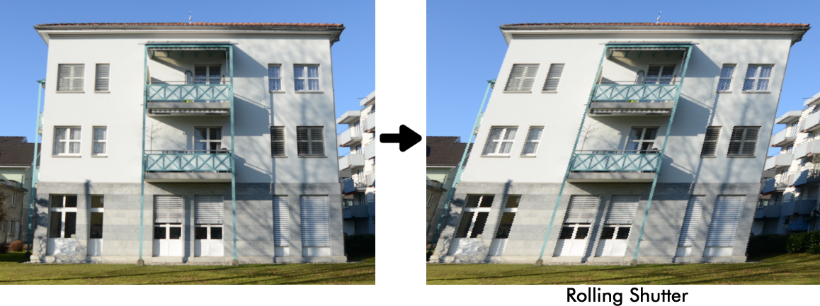
Rolling Shutter Effekt:
When taking photos, most higher-quality cameras expose the sensor at one point in time. For videos, the sensor is read out line by line. When the camera moves, the resulting image is "bent" because by the time the last line is read, the sensor has moved from the position when the first line was read. This makes accurate measurements almost impossible, the image is bent in unpredictable ways:
Rolling shutter effect caused by fast camera movement bending the image.
This website uses cookies
Select which cookies to opt-in to via the checkboxes below; our website uses cookies to examine site traffic and user activity while on our site, for marketing, and to provide social media functionality. More details...
Cookie settings
We use cookies to enhance your browsing experience, serve personalized ads or content, and analyze our traffic. By clicking "Accept All", you consent to our use of cookies. More details...