
Define a System of Coordinates
Overview
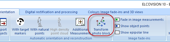
There are several ways to define a coordinate system in an image mosaic, click "Transform photo block":
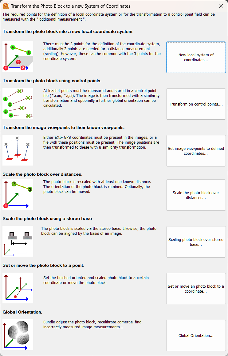
Transform the photo block into a new local coordinate system
Required:
- 3 points that will define the coordinate system: 1 starting point of an axis, 1 point in positive direction on this axis and 1 point that defines a plane with this axis.
- At least 1 known distance, better 2-3 known distances.
Function:
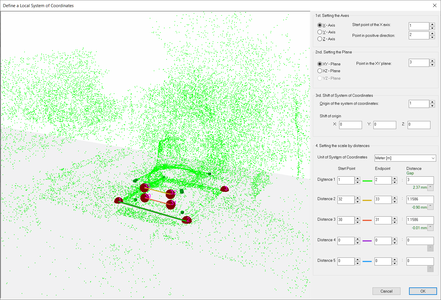
Only point numbers that already exist as object points in the project can be selected. Impossible or non-existent point combinations are displayed in red.
In the 3D view the selected axes are shown as an orange line, the selected plane as a semi-transparent area.
Set X,Y,Z axis, start point of the X,Y,Z axis
With this field the starting point of an axis can be defined. If an axis is defined, those entries in the "Define planes" field are automatically dimmed which are not possible.
Point in positive direction.
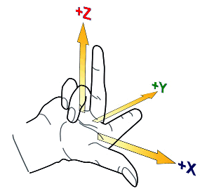
Here a point must be selected which lies in an orthogonal right system in positive direction on the selected axis. If the point is not in the positive direction, the system of coordinates will be upside down.
Point in the XXX plane
With this and the 2 previous points the definition plane of the coordinate system is spanned. It does not have to be somehow "perpendicular" to the other points. However, it should form as large a triangle as possible with the axis definition points.
Origin point of the coordinate system.
This point receives the coordinates 0,0,0 in the new local coordinate system.
Shift in the origin
Here you can enter a shift of the origin point. This can be useful for special applications.
Set scale with distances
At least one distance must be entered here as the scale for the coordinate system. Better are two distances, then ELCOVISION 10 can detect a scale error, best are three distances, then it can identify a wrong input. The gaps to the other distances are shown directly below the input fields, if they are too big they are colored red. The values can be accepted by clicking on ^ button below the edit field.
Unit of the coordinate system
This information is necessary e.g. for printing to scale of rectified images or if you want to export the data from ELCOVISION 10 to other programs.
Notes - Typical Sources of Errors
The distances should be of the same order of magnitude as the object to avoid additional errors due to extrapolation of a small measurement error when measuring the scaling distance:
At least 2 distances should be used: Then the programme can identify an error in the distance measurements. If 3 or more distances are used, the software can identify the distance with the biggest error.
The most common errors are:
- The end points of the distances have been measured at an incorrect point.
- An error was made when noting the distance, mostly transcription errors such as transposed numbers.
- When using levelling staffs: One of the staffs was not fully extended..
Transform or georeference the photo block to a control point field
Required:
- Minimum 4 control points measured in the images, well distributed over the object
- Control point file in ELCOVISION 10 .coo format or Leica GSI format
Function:
The photo block is transferred to a new coordinate system with a similarity transformation.
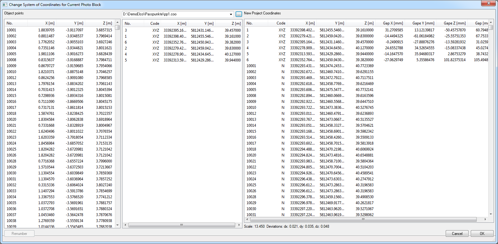
In the left column of the dialog you see the coordinate values of the object points in the current coordinate system, in the middle column the coordinates of the control point file, in the right column are the transformed coordinate values and the remaining gaps at the control points. If the dialog is closed a new global orientation is optionally performed. This allows to find and eliminate the remaining gaps and faulty measurements and to increase the accuracy.
Notes
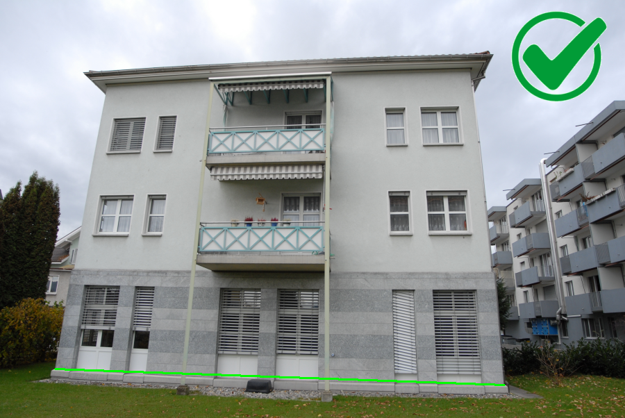
For terrestrial photography, e.g. buildings: The control points should be well distributed over the object and, if possible, also be at different heights, 4-5 points per façade should be measured.
Aerial photography with drones without RTK - GPS
The following methods work very well:
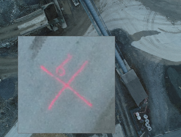
Spray a cross with chalk spray in contrasting colour to the ground and spray the point number next to it, so that point mix-ups are almost impossible:
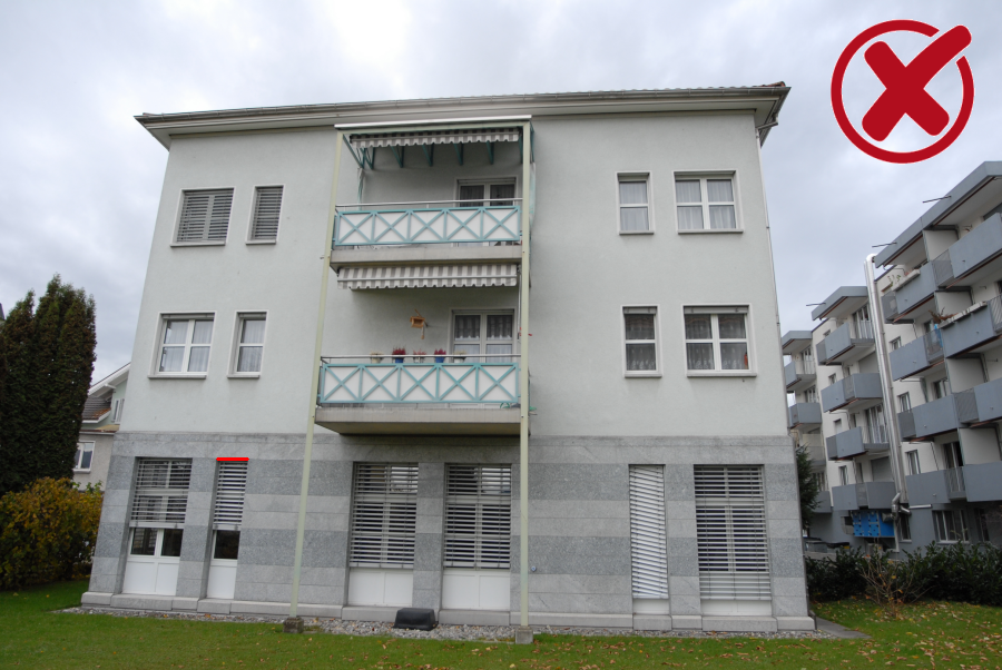
Conventional target boards: Here, however, you have to be careful that the black squares are not faded over:
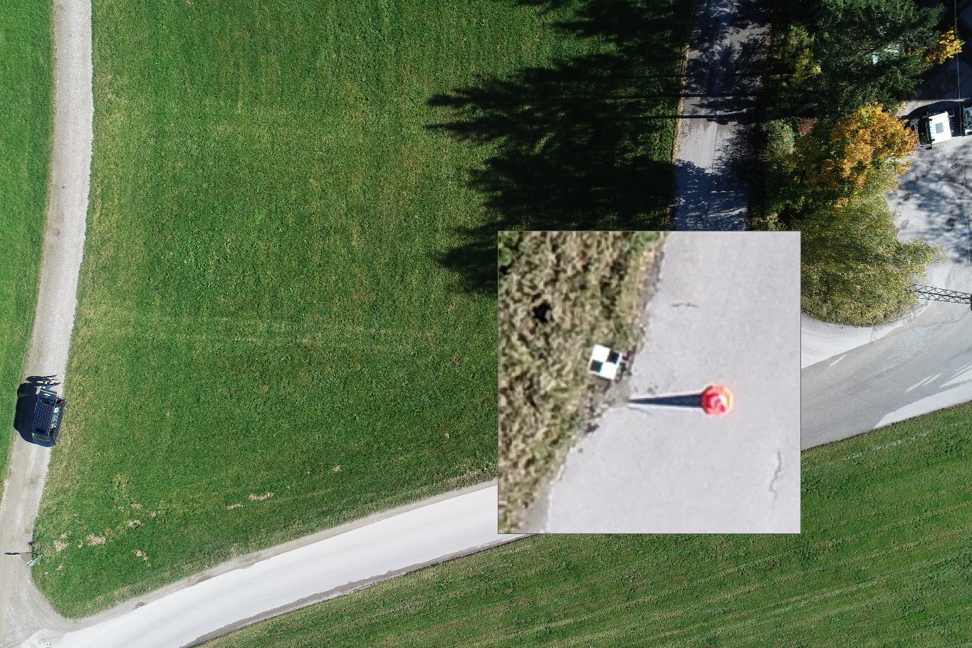
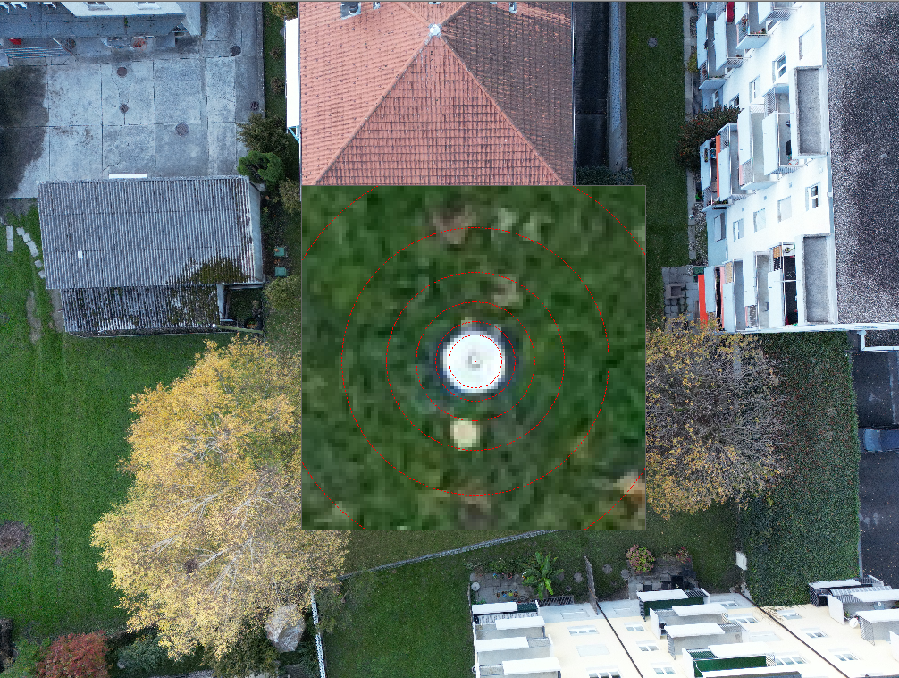
Paint a CD or DVD with a contrasting colour or place it on the floor with the gold or silver side facing upwards and fix it in place. The hole of the CD is an ideal point for a GPS measurement, the CD itself can be measured very precisely with a circular reticle of the magnifying window.
Typical Sources of Error
The coordinates in the control point file are in a left hand system of coordinates:
Symptom: The transformation then either does not work at all or only with very large gaps to the control points..
How to avoid this: Use the GSI file from the instrument, ELCOVISION 10 will then do the transformation into the right coordinate system automatically.
One or more control points have been mixed up or measured at a wrong position:
Symptom: There are also large gaps or the transformation does not work.
Remedy: If more than 6-7 control points have been measured and at least 5 of them have been measured correctly, ELCOVISION 10 usually finds the wrong or mixed up control points and does not use them for the transformation of the photo block.
Transform or georeference the image viewpoints to their known viewpoints
Required:
- Images with GPS information in the Exif data
- or ASCII file with GPS positions of the pictures
Function:
The photo block is transformed into a new coordinate system with a similarity transformation.
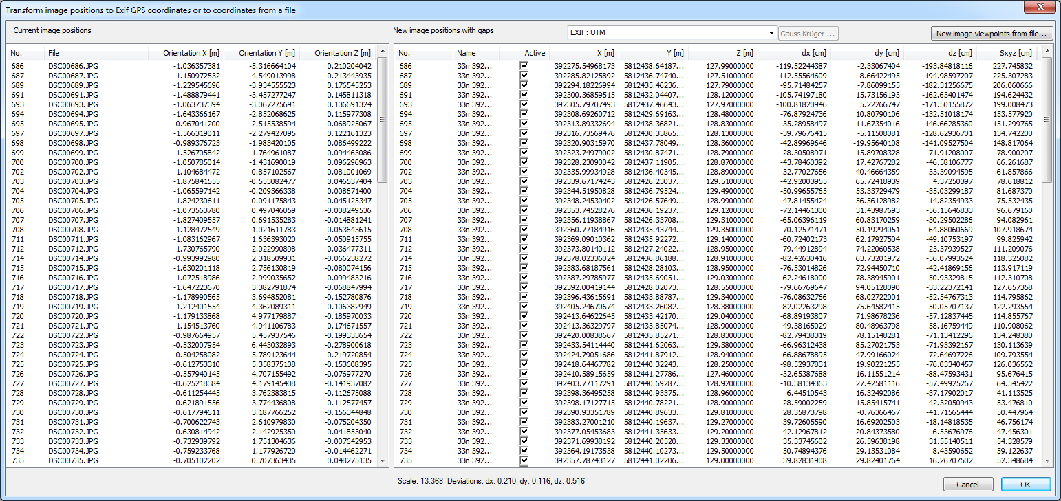
In the left column of the dialog you can see the coordinate values of the images in the current coordinate system, in the right column are the transformed coordinate values of the images and the residual gaps at the image positions. With "normal" drone GPS, gaps in the range of up to 1-10m are normal, due to the poor accuracy of these GPS coordinates. With so-called RTK drones, the gaps are normally less than 10cm.
Outliers are normally detected automatically, you can also switch individual GPS coordinators on/off using the [Active] checkbox.
GPS coordinates can be used as text file, ELCOVISION 10 automatically detects if they are Cartesian coordinates or spherical coordinates.
Data format GPS coordinates - Cartesian coordinates
The file must be an ASCII file. Decimal separator must be a dot. The individual columns must be separated by at least one space or tab or a semicolon.
File_name X Y Z
Example
DSC000113.jpg 55232.211 4733432.231 520DSC000114.jpg 55242.341 4733421.123 521
Data format GPS coordinates - Spherical coordinates
The file must be an ASCII file. Decimal separator must be a dot. The individual columns must be separated by at least one space or tab or a semicolon.
File_name Länge Long Höhe
Example
DSC000113.jpg 22.21132 35.212631 520DSC000114.jpg 22.21138 35.212623 521
Rescale and optionally move the Photo Block
As with the definition of a local coordinate system, the photo block can be rescaled using at least one known distance. If the distances contradict each other, the gaps are also marked in red.
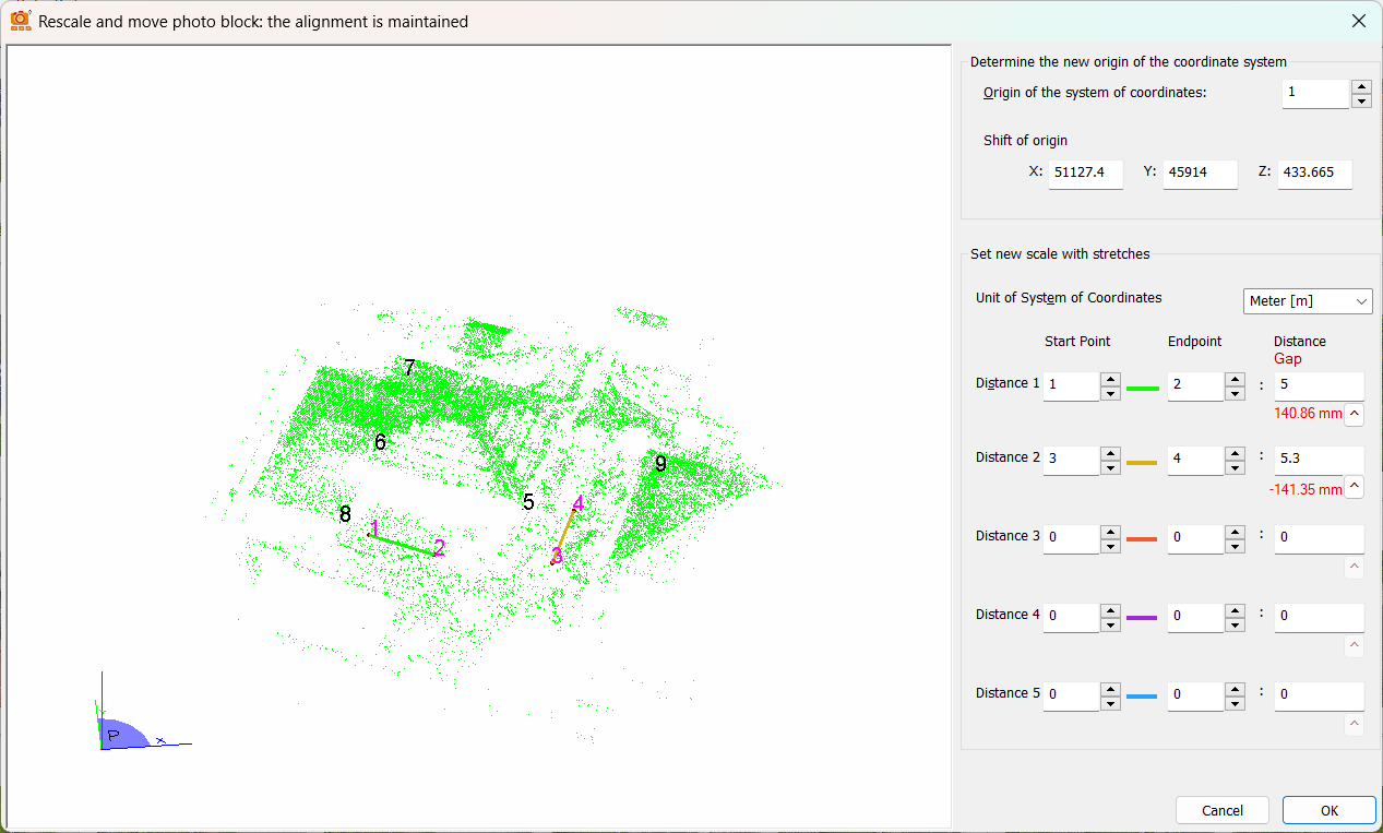
In contrast to the definition of a local coordinate system, the alignment of the photo block is retained. The object point closest to the coordinate origin (0,0,0) is defined as the anchor point of the image association and retains its coordinate.
One application is, for example, the correct scaling of a photo block photographed with a non-RTK drone.
Scaling the Photo Block by Means of a Stereo Basis
A photo block can also be scaled using a known base distance of a stereo camera. In addition, the photo block can be aligned using an image.
If a properly scaled photo block is used, the base distance of a stereo camera itself can be calibrated.
This function can be used for normal stereo cameras as well as for scaling a photo block of spherical cameras that have been made in a high and low position by means of a tripod: Here the base distance is the distance between the high and low position.
If the calibration data of the cameras is not known, the images of the left and right camera must be in different directories so that they can be calibrated separately during the automatic orientation..
This does not have to be done for spherical images if only one camera and/or camera-lens combination was used.
If different cameras were used, the images must also be in different directories if "identical" cameras, i.e. 2 or more identical models, were used. If different camera models and/or objects are used, ELCOVISION 10 will automatically calibrate them separately..
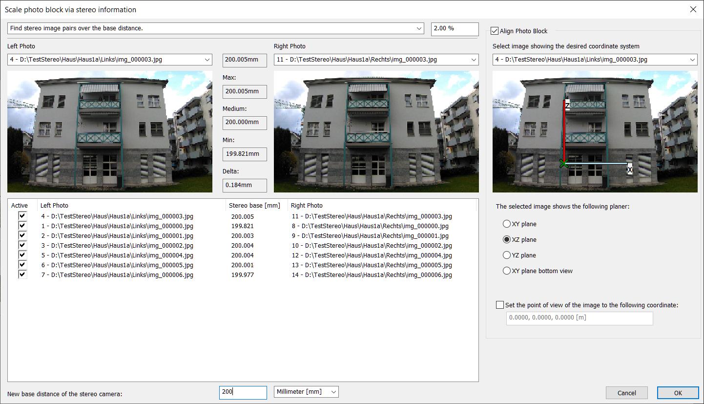
The following methods are available for scaling:
Do not scale photo block, only align.
The scaling of the photo block remains unchanged, but you can select an image that shows the object in the desired coordinate system. The selected coordinate system is drawn into this image for better clarity.
Find stereo image pairs via identical file names. Images must be in different directories.
This is the normal option for stereo cameras. Enter the known base distance in the field below the list "New base distance of stereo camera".
Find stereo image pairs by base distance. Base distance tolerance for the search:
This is the optimal option for all other cases. You can enter a search tolerance, ELCOVISION 10 will search for all other potential stereo image pairs based on the base distance of the selected image pair, e.g. "bottom" and "top" images from spherical cameras.
Enter the known base distance at the bottom into the field below the list "New base distance of stereo camera".
Spherical cameras: distance upper and lower image – images define Z axis - distance tolerance for search:
If the tripod has been calibrated, i.e. the distance between the high and low positions is known exactly, select an image of the upper sphere and lower sphere. For reasons of accuracy, both images should look in the same direction.
A value of 0.2 ... 0.1% should be used as the distance tolerance.
ELCOVISION 10 should now find all ‘stereo image pairs’, if not the following problems may have occurred:
- The pictures were not taken from the "high" and "low" position of the tripod.
- There is a very bad shooting configuration. .
By entering the known base distance in the field "New base distance of stereo camera" the photo block is rescaled.
To align the photo block, it is best to select an image that:
- Looks along the X axis of the object or
- Looks along the Y axis of the object.
If no image is used for alignment, the photo block is only aligned in Z using the top and bottom images; the rotation around the Z axis is random.
Calibration of Stereo Cameras and Base Distances.
To achieve the required high accuracies, you need to set up a test field with ELCOVISION 10 targets; when calibrating normal stereo cameras, a wall like this is sufficient:
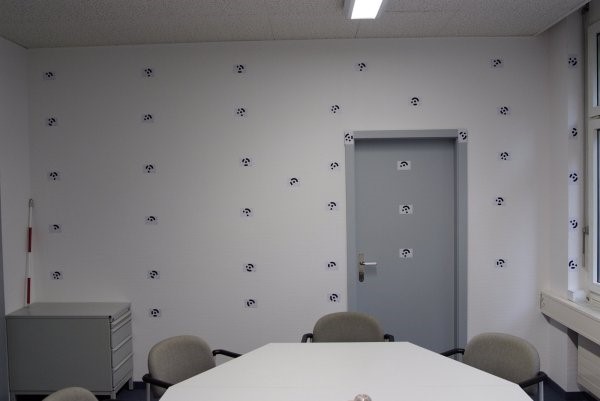
When calibrating base distances of tripods for stereo cameras, the targets should be distributed over at least 2 walls of a room, but preferably over all 4 walls.
There should be at least 10 targets per wall, evenly but slightly "randomly" distributed, they must not be "perfectly" aligned.
These targets must then be carefully measured, this can be done either with a camera that has been calibrated beforehand or by means of a tachymeter. The coordinates of the targets must be saved in a .coo file as full control points.
Calibrating the Cameras and the Stereo Base of a Stereo Camera
Now normal calibration pictures are made, i.e. "normal", "upright - left", "upright - right", and "overhead", one such set of pictures each from 4-5 viewpoints:
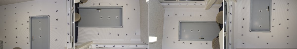
It is important that the images of the left and right camera are saved in different directories! Only then ELCOVISION 10 can clearly distinguish between the pictures of the left and the right camera.
Then the following steps have to be taken:
- Orientate the images automatically using natural points. The recognition of target marks has to be switched on, the camera calibration has to be switched on as well.
- Transform the photo block to the target mark coordinates with "Transform photo block" > "Transform the photo block to a control point field" The residual gap at the control points must be less than 1mm. If not: Use the function "Transform photo block" > "Global orientation" to find and remove the faulty image measurements.
- The camera calibration file "Projectname.cam" should be copied into a suitable directory and activated as the standard camera file in the settings.
When the function "Scale the photo block using a stereo base" is called up, the calibrated base distance is directly visible in the "Medium" field. It is important that the delta, the difference between max and min, should be less than 0.2mm, especially if the base distance is small, e.g. 200mm or less, the delta should be even smaller, here values < 0.1mm should be aimed for. This can be done again by using the "Transform Photo Block" > "Global Orientation".
Calibrating a Spherical Camera
With spherical cameras, the camera should first be calibrated "normally" and then mounted on the tripod in a 2nd step.
Calibrating a Tripod
Set up the tripod in at least 4-5 positions and take "high" and "low" spherical pictures. Make sure that all target marks on all walls are visible in the pictures.
Then the following calculation steps are necessary:
Orient the images with "Automatic orientation with natural points", switch on the detection of target marks here. No camera calibration, the calibration data of the previous camera calibration must be assigned to the camera, this happens automatically when the camera file is selected from Standard camera file in the settings.
Transform the photo block to the target marker coordinates with "Transform photo block" > "Transform the photo block to a control point field". The remaining gap at the control points must be less than 1mm. If not: Use the function "Transform the photo block" > "Global orientation" to find and remove the faulty image measurements.
If the function "Scale the photo block using a stereo base" is called, the calibrated base distance of the tripod is directly visible in the field "Medium". Here, too, the value "Delta" should be less than 0.5mm to achieve good absolute accuracies.
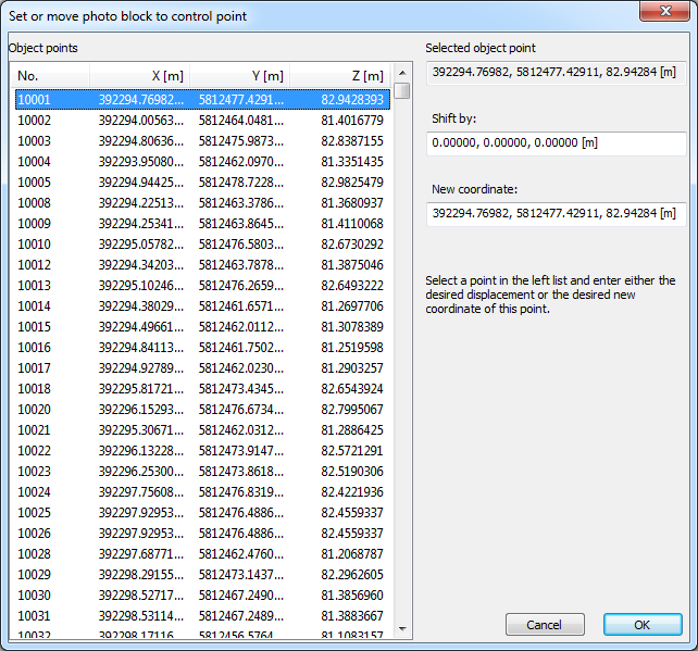
Set or move the photo block to a point
This function is useful for various special applications, e.g. for accurate transformation of image sets taken at different times. You can either enter a displacement or new coordinates for a freely selectable point, the fields in the dialog are then automatically updated accordingly.
Global orientation
Here, photo blocks can be manipulated, cameras can be recalibrated and faulty image measurements can be found.