
Configuring ELCOVISION 10
Configure toolbar
The toolbar above the Ribbon can be freely configured, the most frequently used commands can be added and then the Ribbon can be minimized for this purpose.
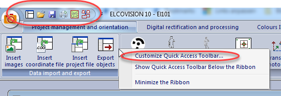
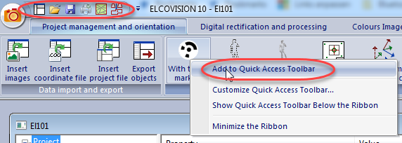
Or by right-clicking on a command button, it can be added directly to the toolbar for quick access:
The visual style of the software can be set using the "Style" button in the upper right corner:
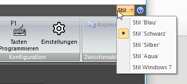
The small blue question mark button next to it opens the license dialog with information about the activated modules.
ELCOVISION 10 Settings
For all values in ELCOVISION 10 there are useful presettings which can be restored for each page with Default Values. Some settings should be changed by the user, these are marked green in the following.
Page General
Automatically load the last edited project after start
If this option is active the last loaded project will be reloaded automatically when ELCOVISION 10 is started
This setting is globally valid for all ELCOVISION 10 projects.
Automatically reload images of a project
If this option is active, all images are automatically reloaded after loading a project and positioned at the position on the screen where they were when the project was last saved.
This setting is globally valid for all ELCOVISION 10 projects.
Save current project periodically / Save Interval / Backup
Here you can specify whether a project should be saved automatically. This option is highly recommended.
ELCOVISION 10 automatically saves the project file (.proX) and the last project file under the name Project_Backup_XXXXXX.proX. Here you can specify how many of these backups should be kept..
This setting is globally valid for all ELCOVISION 10 projects.
Create detailed log file
If this option is checked, the project name.log contains even more detailed information about the calculation progress.
This setting is globally valid for all ELCOVISION 10 projects.
Acoustic feedback
Here you can set if ELCOVISION 10 should acknowledge each manual measurement with a beep or not.
This setting is globally valid for all ELCOVISION 10 projects.
Camera File / Standard Camera
Here you define the path to the default camera file and select the camera to be suggested as the default camera in the orientation dialogs.
If you use "Automatically assign camera if possible" ELCOVISION 10 selects the best fitting camera from the camera file using the Exif or Tiff information.
It is recommended to combine all camera data in one single file.
This setting is globally valid for all ELCOVISION 10 projects.
Exif Tag Additional Information
If you have more than one camera of the same design or if there are more than one camera in the camera file ELCOVISION 10 can automatically assign the right camera by an additional Exif Tag. For example the "Author" or "Copyright" field can be set in the camera:
In the camera file the name of the camera must contain the text which is set in the corresponding Exif Tag.
For example, if "IPTC Caption" is set to "KAM1", the corresponding entry in the camera file must be like this:
{ 14 33.487 -0.068265 -0.248052 -7.55607e-05 2.05857e-07 9 "KAM1 FinePixS2Pro 35mm"}
This setting is globally valid for all ELCOVISION 10 projects.
Standard Réseau
This file is automatically suggested for an image when the réseau measurement is started.
For digital cameras there is the "digicam.dres" file in which the CCD sizes for all known cameras are stored. This is the default setting for all digital projects. If a digital camera is not known, the digicam.dres must be updated. This is best done by sending a picture of the camera to the PMS AG..
This setting is globally valid for all ELCOVISION 10 projects.
Page Measurement Limits
Detection barrier Réseau measurement
This setting is only used for scans of analog images with réseau crosses:
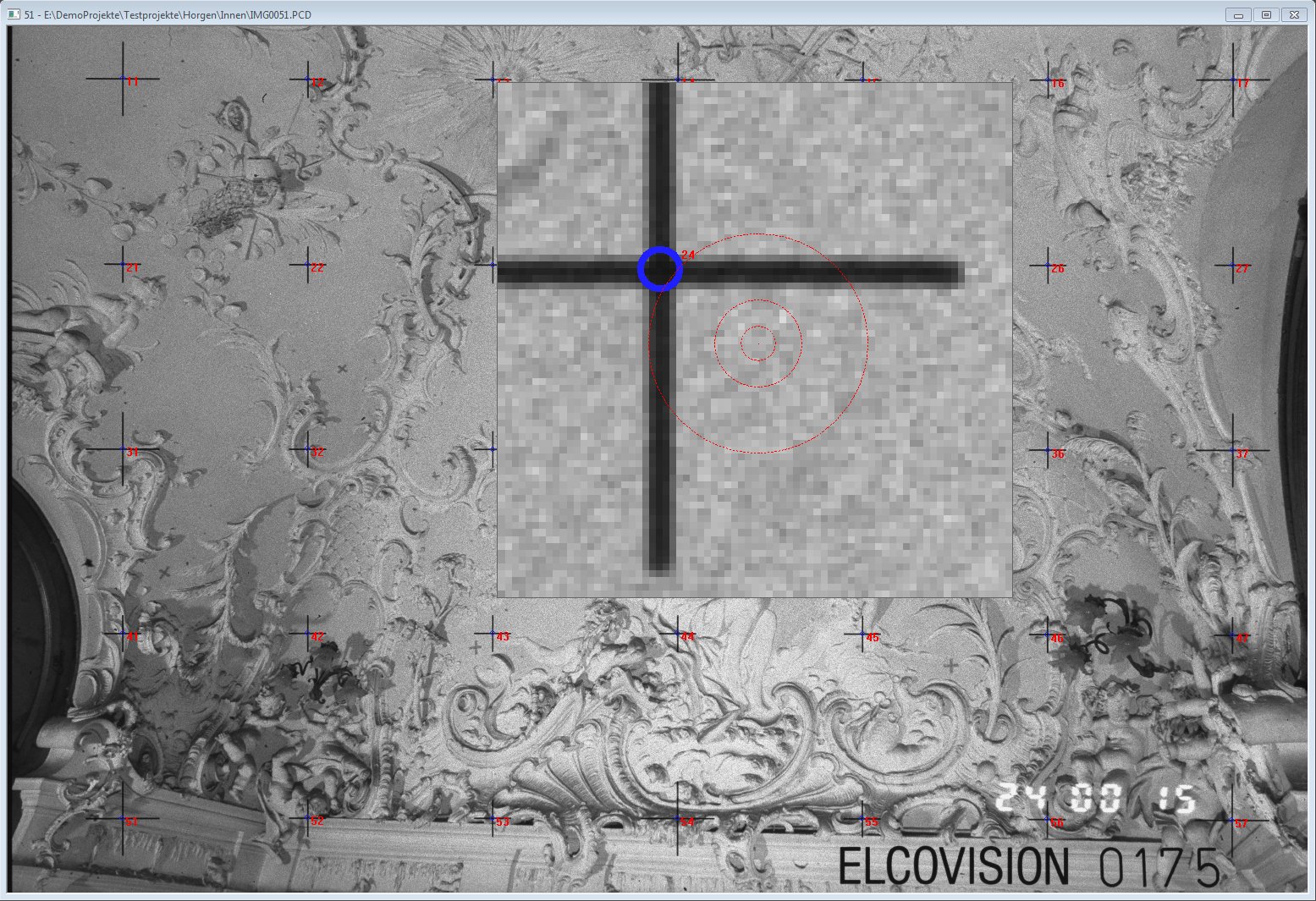
If a réseau cross is measured manually ELCOVISION 10 searches for the nearest réseau cross which could fit to this measurement. This réseau cross will only be accepted as the correct one if the measurement does not deviate from the target position by more than the set value.
This setting can be assigned for each ELCOVISION 10 project individually.
Error Vector Threshold Réseau Measurement
For each réseau measurement, all deviation vectors are recalculated for all measured réseau crosses. To make it easier to detect gross measurement errors, those deviation vectors whose absolute value is below this limit are automatically faded out in the réseau measurement
This setting can be assigned for each ELCOVISION 10 project individually.
Maximum allowed point deviation
If this threshold is exceeded during a manual point measurement ELCOVISION 10 will display a warning dialog..
This setting can be assigned for each ELCOVISION 10 project individually.
Page Images
Enlarge digital images to the following value during the 1st loading proces
Digital images are automatically reduced or enlarged to this percentage when loaded for the first time. Favorable values for the size are 15% to 25% depending on the screen resolution.
This setting is globally valid for all ELCOVISION 10 projects.
Delay time until an automatic measurement is suggested
ELCOVISION 10 works with some image recognition methods. During the réseau measurement the measuring magnifier automatically snaps to the nearest réseau cross after the time set for this.
This setting is globally valid for all ELCOVISION 10 projects.
Compression when writing JPG
Here you can set the compression factor for writing JPEG image files. The higher this factor is, the smaller the resulting files become, but the higher the compression artifacts in the images.
This setting is globally valid for all ELCOVISION 10 projects.
Rasterize images with ELCOVISION 10
With this option the raster process for printing digital images can be taken over by ELCOVISION 10. If you use older printers for printing images the internal memory of the printer can be overloaded because of the huge amount of data. This can be solved by activating the rasterizing function in ELCOVISION 10. But the image quality of the printout can suffer because the printer does not take into account the specific characteristics of the printer as it is the case with the manufacturer's printer driver for a printer.
This setting is globally valid for all ELCOVISION 10 projects.
DPI value when printing images
Here you can select how many DPI ELCOVISION 10 should rasterize an image for printing. The higher this value is the finer the resolution of the image.
This setting is globally valid for all ELCOVISION 10 projects.
Page from Kodak Photo CD
A Photo CD contains multiple resolutions per image file. Normally, however, the same one is always used, and this can be set here.
This setting is globally valid for all ELCOVISION 10 projects.
Page for multi-page images (except Photo CD)
There are several image data formats that can contain multiple images in one file: Tiff, Gif, PNG etc. Most of the time a thumbnail and the image is kept in full resolution. Here you can set that the image with the highest resolution is always used.
This setting is globally valid for all ELCOVISION 10 projects.
Page Orientation
Maximum number of iteration steps until abort
After reaching the set number of iteration steps, the global orientation is terminated. If no solution is found after a large number of iteration steps, this always indicates a poor point distribution or weak acquisition geometry..
This setting can be assigned for each ELCOVISION 10 project individually.
Additional iteration steps for a camera calibration
The Global Orientation is here granted further iteration steps to calibrate the camera.
This setting can be assigned for each ELCOVISION 10 project individually.
Image Coordinate Accuracy
The accuracy of the image coordinates depends on the measuring instrument used or its resolution. This information is important for the accuracy calculation and the relation of image measurements to geodetic measurements such as additional observations and control points.
This setting can be assigned for each ELCOVISION 10 project individually.
Accuracy of control points
This is the accuracy with which the control points have been determined. The accuracy also indicates to what extent the control point coordinates exert constraint on other observations.
This setting can be assigned for each ELCOVISION 10 project individually.
Threshold display Image coordinate deviation
Only image measurements whose deviations exceed this limit are displayed in the Global Orientation results dialog.
This setting can be assigned for each ELCOVISION 10 project individually.
Page Manipulation
Here the current project can be manipulated in various ways.
Page CAD
Directory in which the images should be saved
If images are rectified for CAD drawings, they are usually only referenced by the CAD program. This can lead to problems if the CAD files have to be moved. This option can be used to minimize these problems.
In AutoCAD/BricsCAD the option "eTransmit" is very useful to bundle all images and other external references of a drawing in one zip file.
This setting can be assigned for each ELCOVISION 10 project individually.
Reduce pixel effect
If images are rectified normally, "pixelated" images are created, edges and transitions become "stair-like". These effects can be suppressed by ELCOVISION 10 by a special procedure where details are not blurred. But the computing time for an equalization increases noticeably..
This setting can be assigned for each ELCOVISION 10 project individually.
Pixel Size
If many different rectification layers from different images are transferred as textures into the CAD, each of these images has a different pixel scale or pixel size. This can lead to visually inhomogeneous images. With this setting the pixel scales of the individual rectified images can be adjusted to each other.
This setting can be assigned for each ELCOVISION 10 project individually.
Page Colors
Here you can define the colors for the different image displays. These settings are also available in the ribbon bar.
This setting is globally valid for all ELCOVISION 10 projects
Programming the keyboard
The keyboard layout of the following commands can be freely programmed:
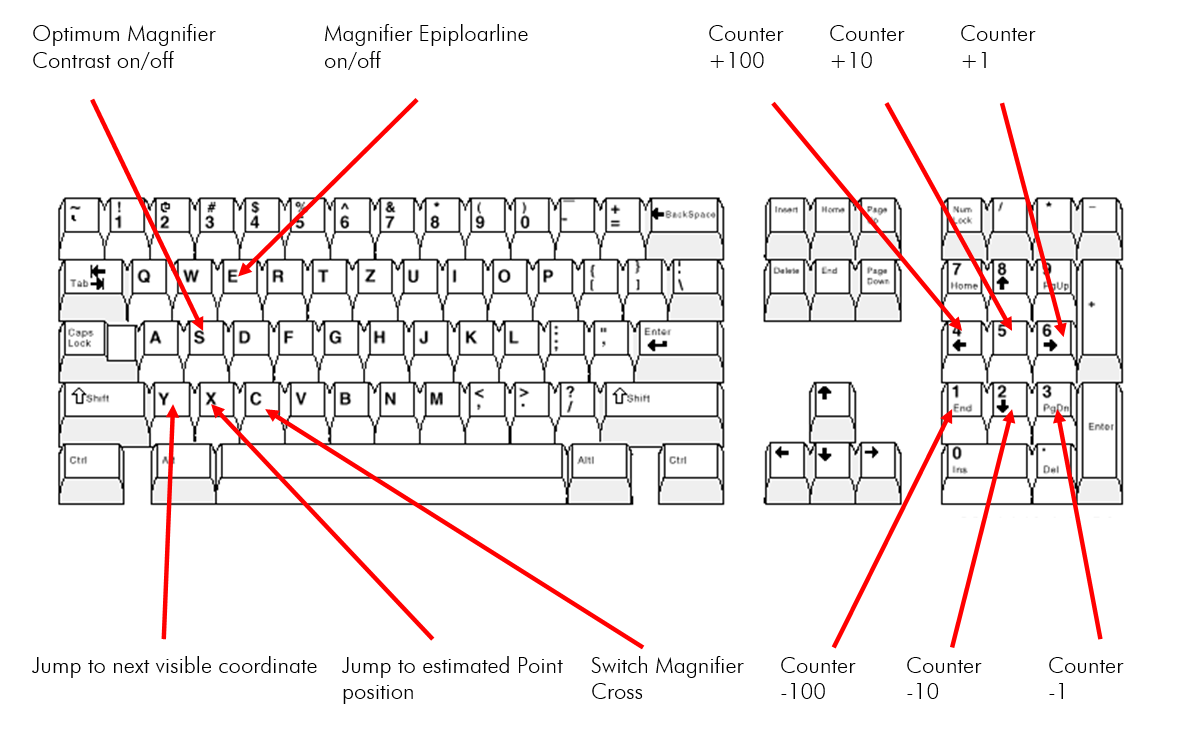
Start the Program Keys function. Select the desired function, move the mouse pointer into a digital image and press the desired key. The function is then programmed to this key.