
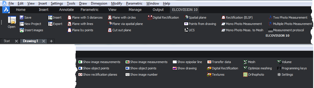
ELCOVISION 10 Plugin
Overview
All measurement results of ELCOVISION 10 will be transferred directly to the AutoCAD /BricsCAD command line as if you would enter them manually. This means that you can apply coordinates from ELCOVISION 10 to almost every drawing command of AutoCAD /BricsCAD.
The coordinates that ELCOVISION 10 determines for a point are automatically converted into the current user coordinate system.
Some drawing commands of AutoCAD /BricsCAD only accept 2D coordinates. With the ELCOVISION 10 Tools 10 Tools there is another plugin available which provides 3D variants and other useful drawing commands.
To start the ELCOVISION 10 Plugin enter the command "elcovision" or "elcovisiondemo" in the command line of AutoCAD /BricsCAD:
Measurement window
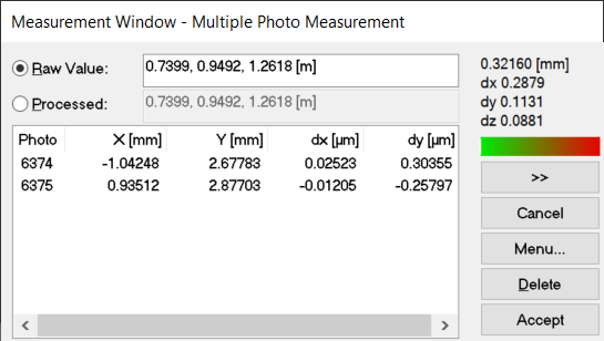
The Measurement Window is the main control element for the measurements in ELCOVISION 10 and appears automatically when you start the plugin and cannot be switched off.
Title bar
The current measuring mode is displayed
Raw value
If this switch is active, the coordinates that have not been further processed are taken over as 3D point.
Processed
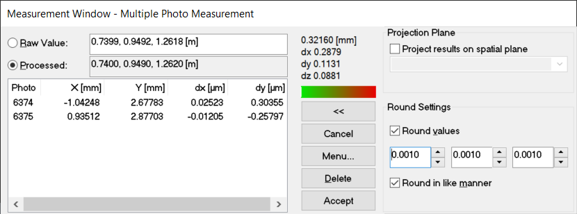
If this switch is active, the coordinates are revised as specified and this determined 3D point is then forwarded to the corresponding instances.
Coordinate field Raw Value
The calculated 3D coordinates are output here. You can also enter your own values here and accept them using the [Accept] button. However, the coordinates (raw or processed) that are currently active will be accepted and transmitted.
Coordinate field Processed
Here the processed coordinates, i.e. the projected or rounded coordinates, are displayed. However, those coordinates (raw or processed) which are currently active are taken over and transmitted.
Point error field
If possible, the calculated point error of the measured 3D point is output here. The point error is additionally split into the x,y,z value.
List field
This list contains all measured image points (in mm) from which the 3D coordinates of the object point are calculated. If a calculation of the point error is possible, the differences at the individual pixels are displayed.
Cancel
With this button a measurement can be stopped, but not a drawing command from AutoCAD / BricsCAD
Accept
The multi-photo measurement for the respective point is completed with this button and its 3D coordinates are accepted.
Delete
Deletes the selected image measurement(s) in the list box.
Menu
A menu of the most important measuring commands appears.
Projection of measurements on any plane
Any 3D coordinate generated by a measurement or input into the coordinate field can be projected onto any plane. The spatial planes that can be generated with the known methods serve as projection planes.
The projected point is the base point of a point on this plane.
Project Results on spatial plane
With this switch the projection on a plane can be switched on and off generally.
List with projection planes
Any spatial plane can be selected as projection plane.
Round values
Here you can set to how many decimal places a measured value should be rounded.
Automatic rounding of measured values
As a second processing step, determined 3D coordinates can be rounded to any value. The rounding can be set separately for all three coordinate values. The rounding value X determined by ELCOVISION 10 is in the range
X1 <= X <= X2
Whereby
X1 = measured value - rounding value/2
X2 = measured value + rounding value/2
is.
Round Values
With this switch the rounding mode can be switched on and off in general.
Rounding values for X,Y,Z
Here you can specify the rounding values for the individual coordinate axes.
Round in like manner
If this switch is active, all rounding values are immediately updated when one of them is changed. If the switch is not active, the rounding values can be set separately for all coordinate axes.
Drawing using image measurements
- Load the images in which you want to measure by double-clicking on the overview images in the project manager.
- Arrange the drawing window and the images sensibly on the monitor.
- Start the desired drawing command, here we use "line" as an example.
- If necessary, switch to one of the desired measuring modes, here we use the two-image measurement: The measuring mode can be switched at any time in the ribbon or in the Measurement Window - [Menu...].
- Measure the first point in both images, the result is automatically transferred to the CAD command line. The line command starts the line at this point.
- Measure the second point in both images, the result is automatically transmitted to the CAD command line. The line is now 1 segment long.
- The line can be extended with any number of measurements.
Video
Things to know
- Almost every drawing command of the CAD can be fed with the results of image measurements.
- The measurement mode can be changed for each point: For example, the first point can be created by a multi-image measurement, the second with a single-image measurement, the third with a two-image measurement, etc.
- The ELCOVISION 10 tools have numerous additional drawing commands that are optimised for surveying tasks.
Superimposing a Drawing into the Images
For documentation purposes or for further analysis, a drawing can be superimposed into oriented images.
- Start the command Superimpose Drawing into Images
- Start the select command in the dialogue that appears
- Select the drawing elements in the drawing that are to be superimposed.
- Press Enter in the command line to return to the dialogue.
- The selected drawing elements are now superimposed in the images.
Video