Getting Started Guide
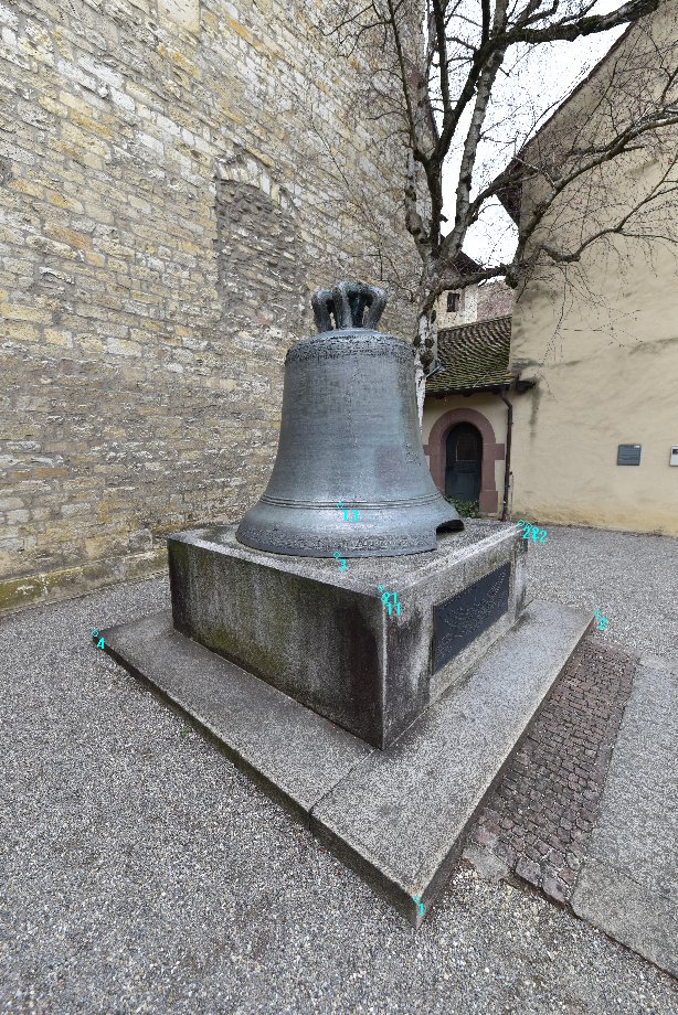
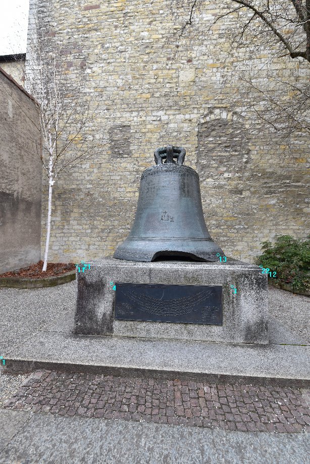
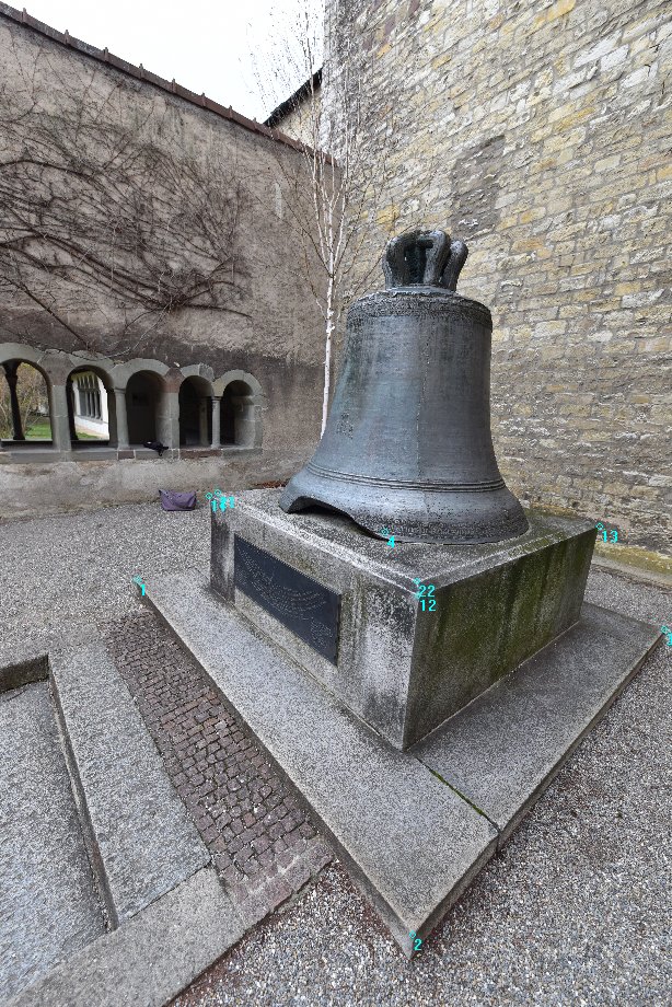
In this example, the images of the Schillerglocke in Schaffhausen are evaluated.
Image import, fully automatic orientation, the generation of a high-density point cloud, definition of a local coordinate system and some evaluations of the high-density point cloud are shown.
Example Images and Demo Project
You can download the images for this example here:
https://www.elcovision.com/ExamplesHD/SchillerGlocke_IMG.zip
A completed project with high density point cloud can be found here:
https://www.elcovision.com/ExamplesHD/SchillerGlocke_PRO.zip
You can find more examples for calculating yourself here:
https://en.elcovision.com/elcovision-10-beispiele.html
Use your own pictures
If you want to take pictures yourself, make sure that any point of the object is visible in at least 3 pictures from different perspectives: Here you will find instructions on how to take pictures best and what to pay special attention to.
Abstract - Use your own pictures
- Do not take pictures from the same point of view. Move one step to the side for each picture.
- The pictures can be taken with any camera. The higher the quality of the camera, the better and more accurate the results.
- Do not zoom around. It is best to use fixed focal length lenses, for zoom lenses use wide angle stop or telephoto stop.
- Turn off the camera's auto focus: Focus the lens before taking the first picture. If you cannot switch off the autofocus, you must have each image calibrated separately in the "Automatic orientation" step. However, the accuracy of the evaluation will then decrease.
- The images must have at least 75% overlap, if the surface of the object is very jagged better more.
Start ELCOVISION 10

Drag-and-drop Images into the Software
A new project and thumbnails of the images will be created automatically. The images are prepared for automatic 3D reconstruction:
If the camera ELCOVISION 10 is unknown, select a suitable CCD size from the dialog "CCD size for unknown digital camera". This size should come close to the correct CCD size, or ELCOVISION 10 may not be able to orient the images correctly. It is best to send us such an image and we will add the CCD size to the CCD sizes file.
If the project window does not appear during loading, it is hidden somewhere in the background. At the top of the [Ribbon > Project Management and Orientation > Windows] select either Cascade Windows or Tile Windows.
Start the Automatic 3D Reconstruction
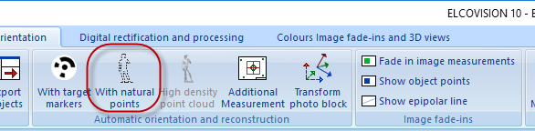
Start the automatic reconstruction with "Automatic orientation and reconstruction" - "With natural points".
A "Save as" dialog box appears. If possible save the project to a local hard disk, preferably an SSD with enough free space for the temporary data created by ELCOVISION 10.
The first page of the orientation wizard appears:
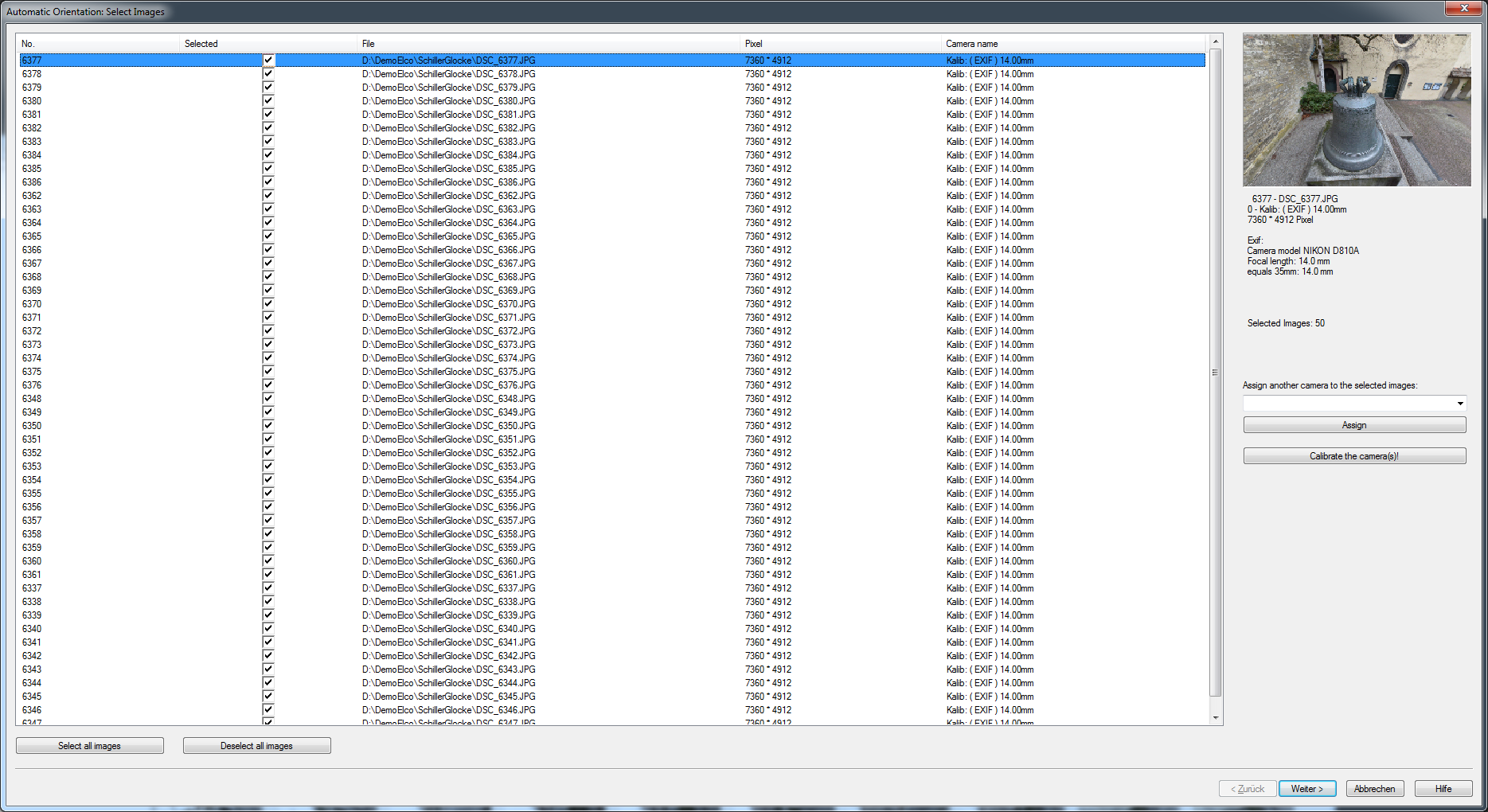
Press Next >. The Camera Calibration Settings page appears:

If you took pictures yourself and the camera was refocused during shooting, uncheck "Together" in the camera list.
Press Next >. The final configuration page for automatic orientation appears.
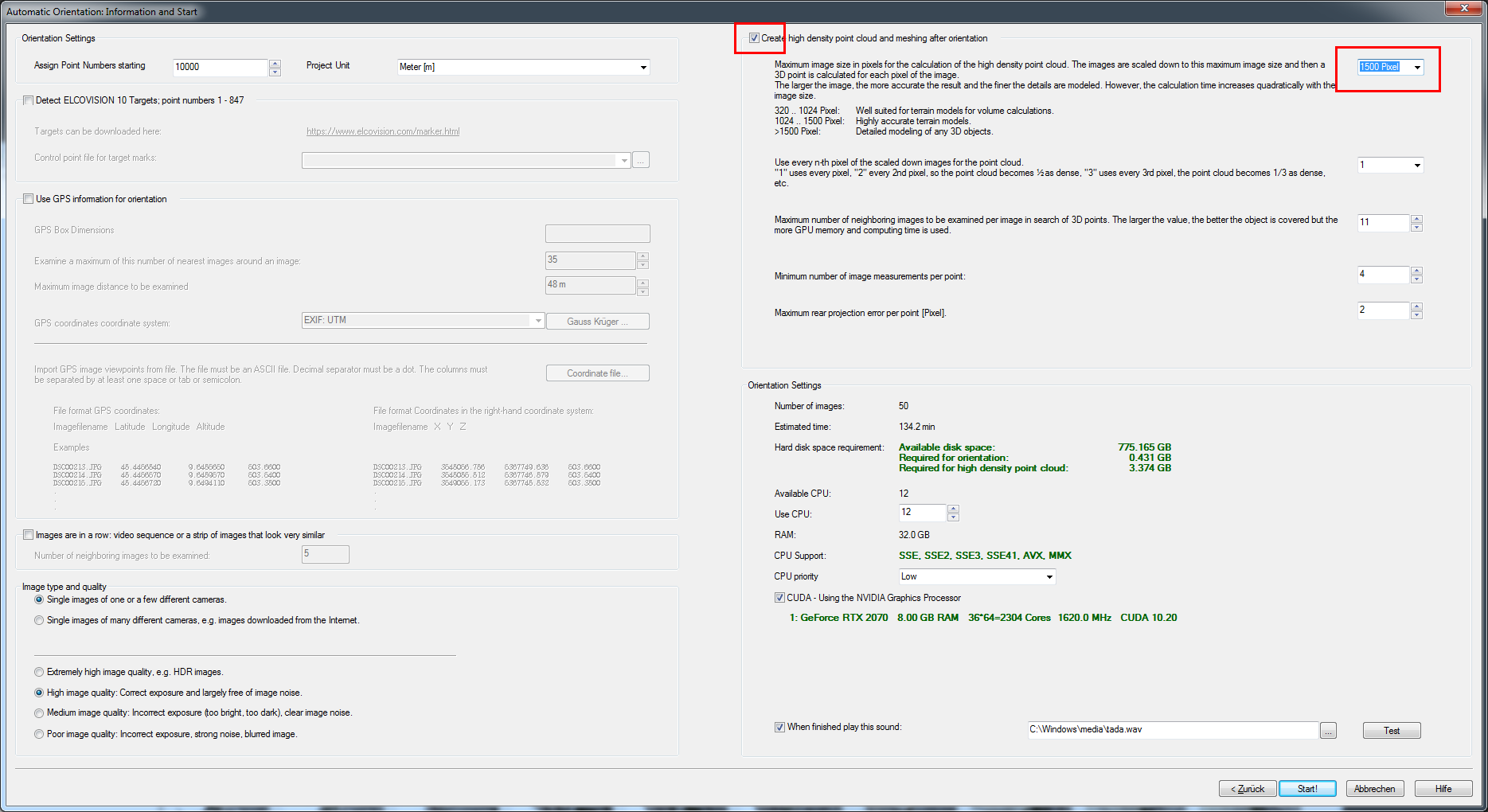
For this example we also calculate a high-density point cloud. Activate "High density point cloud" and select a maximum image size of approximately 1500 pixels. This will produce a quite good result and the computing time will still be within a few minutes
Press Start!.
ELCOVISION 10 starts the calculation and displays the calculation progress. After some time you will get the result:
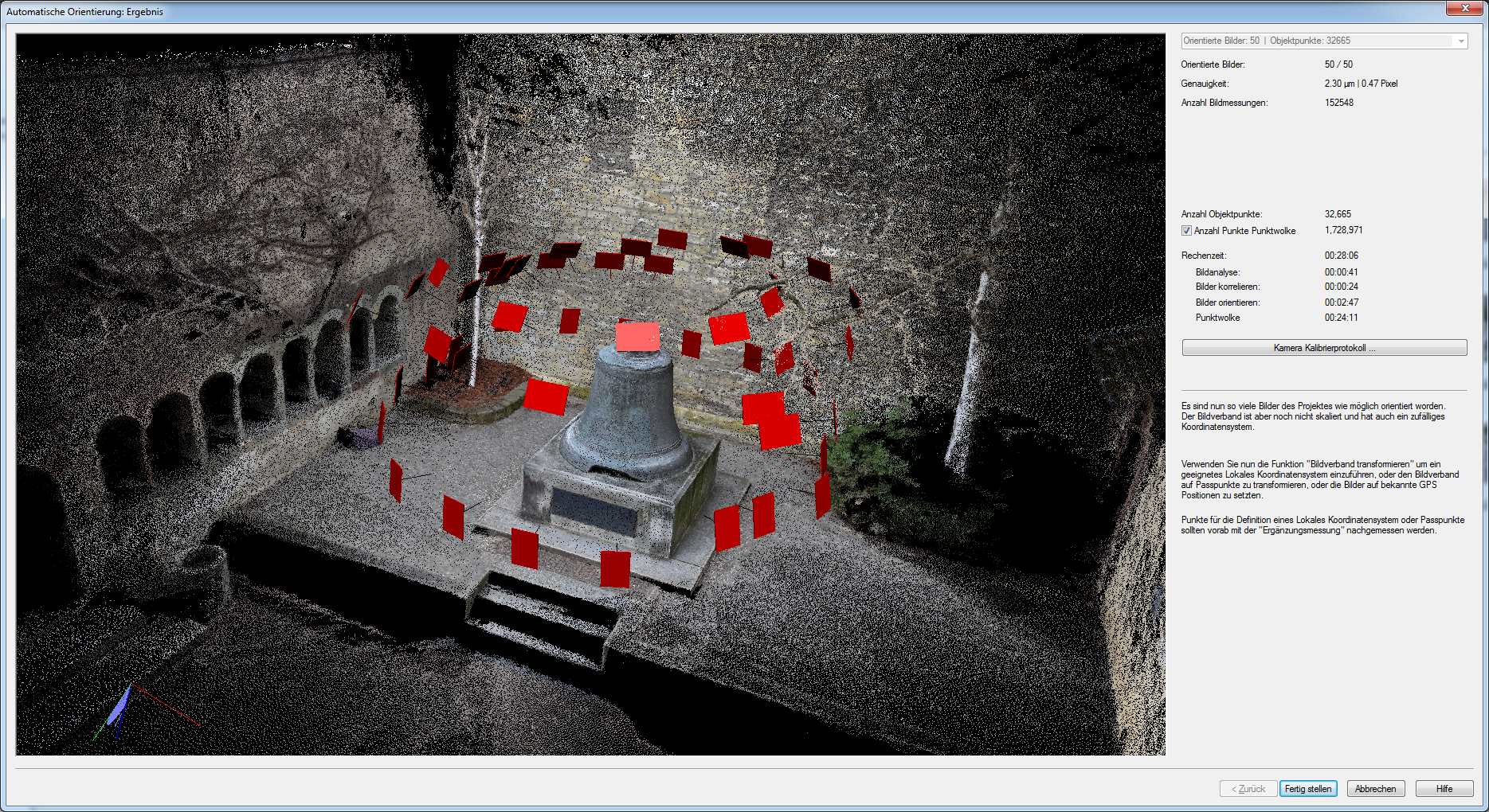
The photo block is now oriented, but the correct scale or coordinate system is still missing. This can now be done by manually measuring points for a local coordinate system or for control points.
Manual image measurements in ELCOVISION 10
Load the images in which you want to measure points by double-clicking on the thumbnails in the project manager. If the images are too big or too small they can be made bigger or smaller with the context menu. Arrange the images neatly on the screen:
In digital images, the mouse pointer is used to measure. If the mouse is moved over a digital image, the mouse pointer is transformed into a measuring cursor, and a corresponding enlargement of the image section around the measuring cursor area is automatically visible in the digital magnifier. The measurement cursor can be controlled in different ways:
| Mouse Movement | The measuring cursor is moved accordingly. |
| Ctrl + Mouse movement | The measuring cursor is moved in 10 pixel steps in the in the magnifier window |
| Ctrl + Cursor keys | The measuring cursor is moved in 10 pixel steps |
| Shift + Mouse movement | The measuring cursor is moved in ½ pixel increments in the magnifier window |
| Shift + Cursor keys | The measuring cursor is moved in ½ pixel increments |
| Cursor keys | The measuring cursor is moved in 1 pixel increments |
| Mouse Wheel | Zoom in/out |
| Ctrl + Mouse Wheel | The magnifier window is enlarged or shrunk. |
| Enter Left Mouse Button | A measurement is triggered |
| Middle Mouse Button | The magnifier is switched on/off. Measurements can only be made when the magnifier is switched on! |
| Right Mouse Button | Context menu in which, among other things, the fixed/flowing magnifier can be selected. |
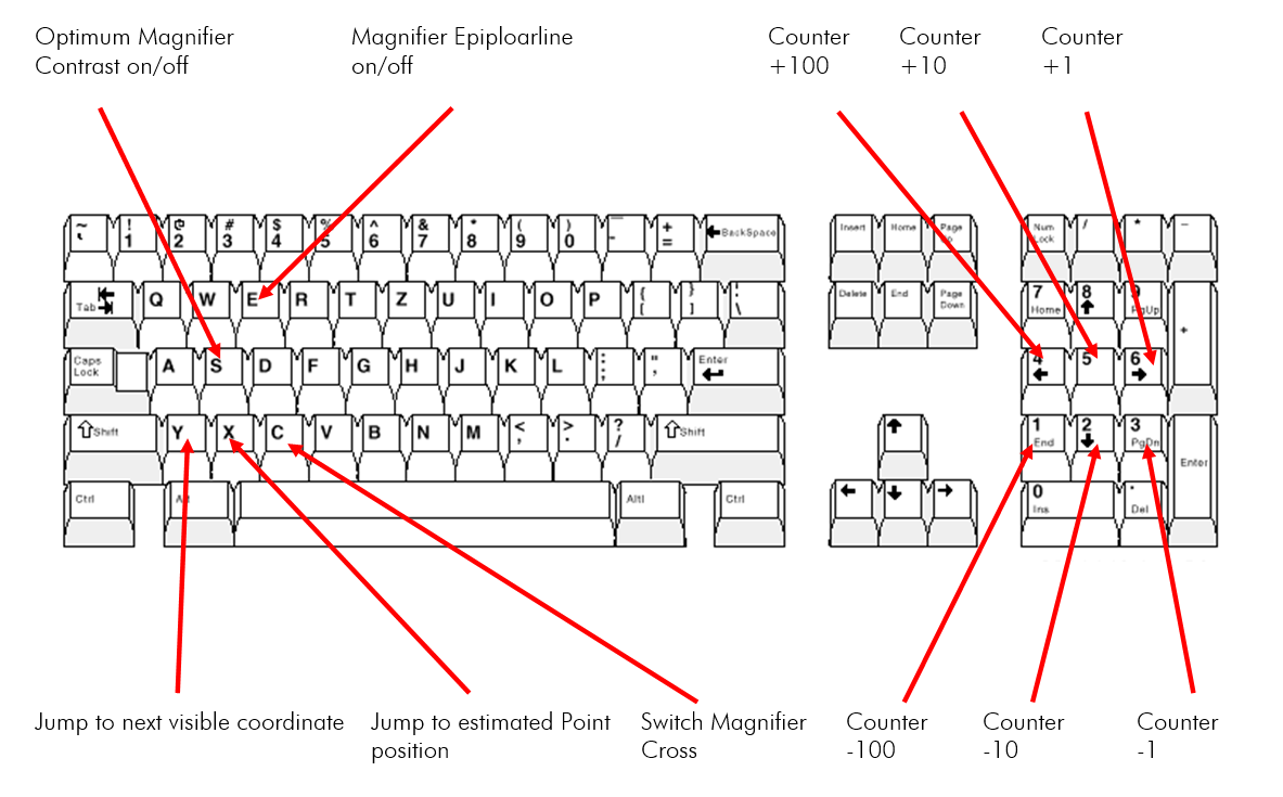
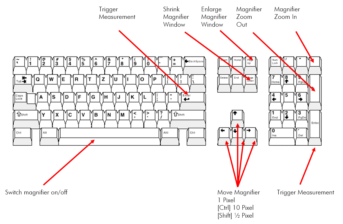
Overview of the key assignment
Recommended precedence when measuring points:
- Move the mouse approximately to the position of the point you want to measure.
- In case of the static magnifier: Let go of the mouse
- Use the cursor keys on the keyboard to fine-tune the point.
- Finish the measurement by pressing Enter. Do not use the left mouse button as this can easily affect the set measurement point.
Manual measurement of additional points for a local coordinate system or for control points
Start the additional measurement:
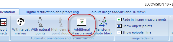
We will measure 3 points for a local coordinate system. Each important point such as points for the definition of a coordinate system should be measured in 3-4 images.
By optimizing the magnifying glass contrast, points in dark image areas can also be measured very well.
Please note that from the 1st measurement on an Epipolar line is displayed in the images which helps to find the point in the other images. From the 2nd measurement onwards, an "X" is inserted into the epipolar line to indicate the probable image measuring point. By pressing the [X] key, you can jump directly to this point. Then the measurement only needs to be fine-tuned:
After 3 points have been measured, a local coordinate system can now be introduced. To be on the same state like in this example, drag the file "SchillerGlocke.imo" which was packed with the image files, and drop it into ELCOVISION 10:
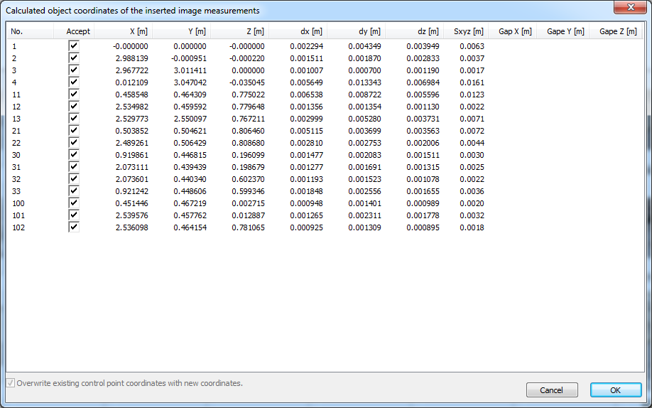
A forward cut is automatically calculated from the imported image measurements and the result is displayed. Afterwards the new points are available as object points.
Definition of a Local System of Coordinates
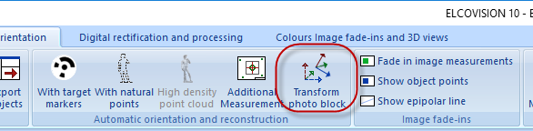
Start the function Transform photo block.
Select the first entry, New local system of coordinates
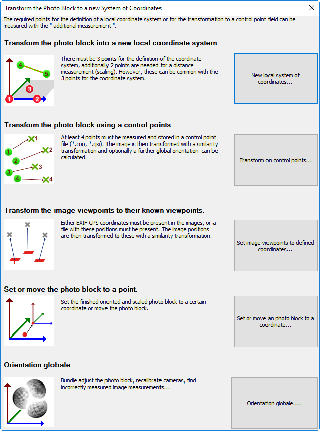
Define the desired coordinate system with the points just measured. The representation of the selected coordinate-system plane in the 3D view and the displayed distances is helpful:
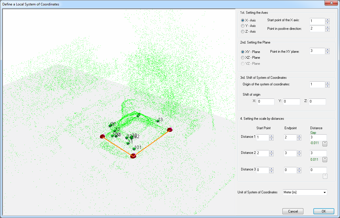
Enter the following data as shown above, most of the data for the alignment of the coordinate system should already be entered automatically:
1. Setting the Axes
- Starting point of the X Axis: 1
- Point in positive Direction: 2
2. Setting the Plane
- Point in the XY plane : 3
With this, the XY plane is placed on the ground, so this object is sufficiently well horizontalised.
3. Shift of System of Coordinates
- Origin of System of Coordinates: 1
- Shift of origin: 0,0,0
4. Setting the scale by distances
- Distance 1: Start Point 1 - End Point2, Distance 3m
- Distance 2: Start Point 2 - End Point3, Distance 3m
The residual gaps are shown in green or red under the input fields of the distance. Here the residual gaps are green, i.e. there is no scaling error.
Now the photo block is scaled and in the correct system of coordinates and can be evaluated.
Subsequent Generation of a High Density Point Cloud
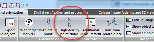
A new high-density point cloud can be added at any time. The first step is "High Density Point Cloud" in the ribbon bar:
Select from which images the high density point cloud is to be generated and how high resolution it is to be. Experiment a little with the different resolutions. In this example you will get a very detailed point cloud from 2500 pixels resolution on:
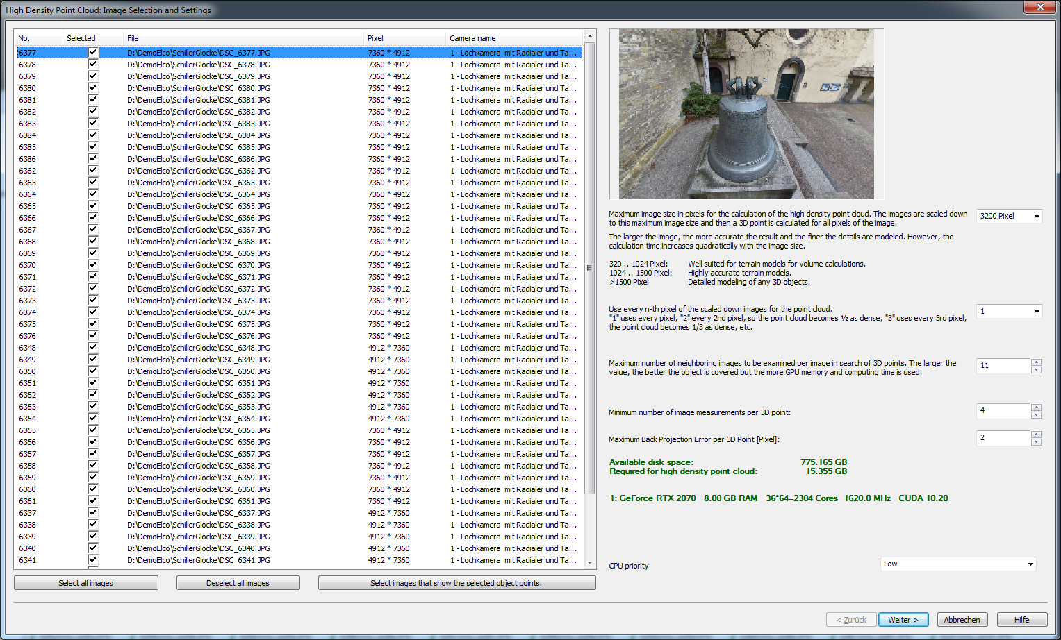
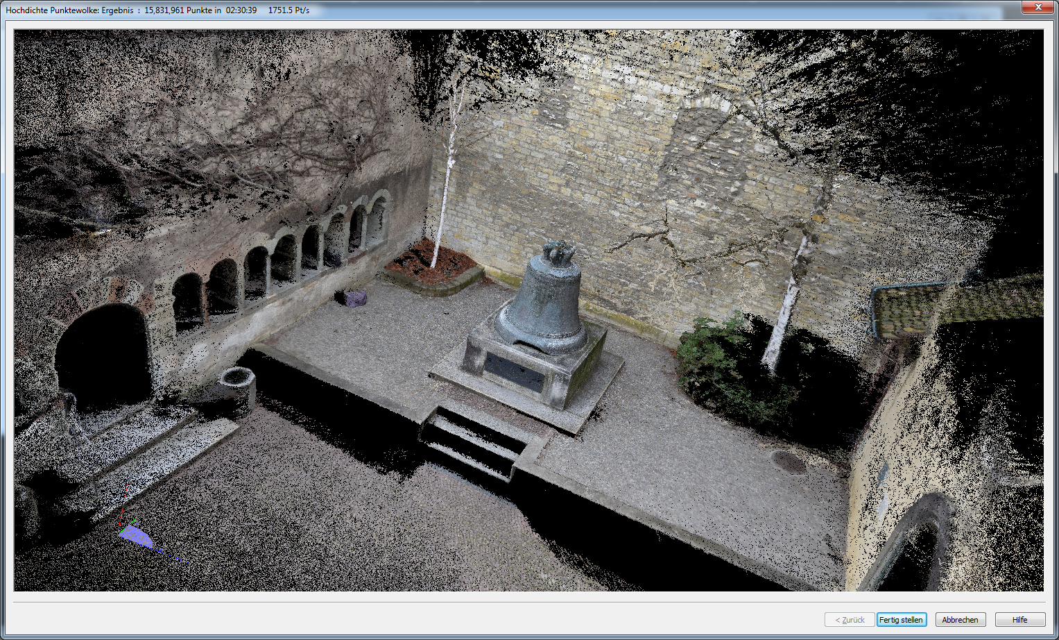
Then press Start!. After some time you will get the result:

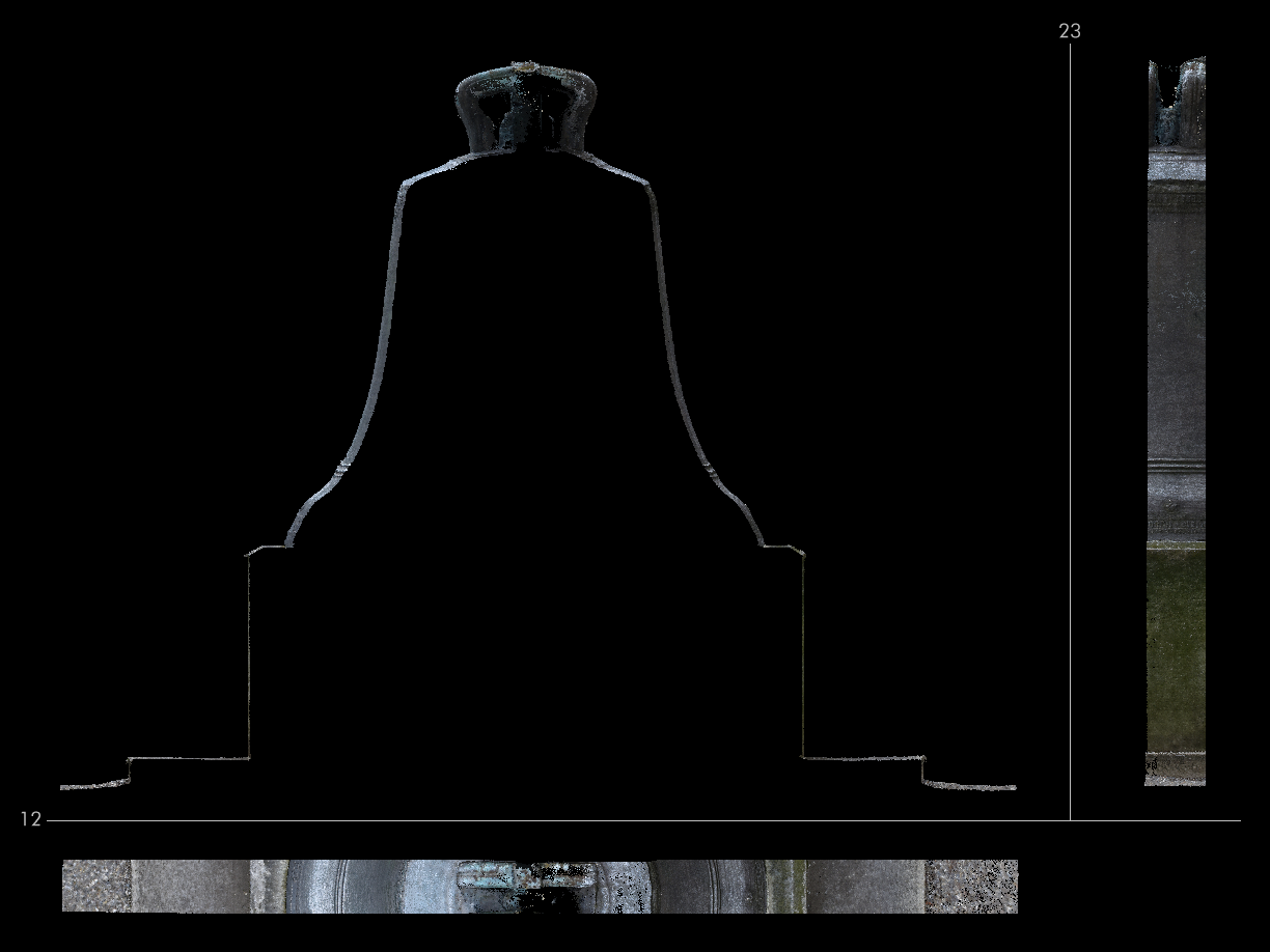
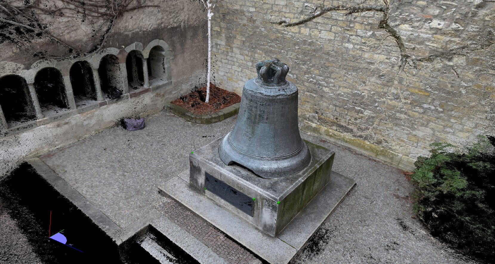
Assessment of the Quality of the Point Cloud
If you accept the result with OK, you can cut out the bell in the project manager or move it to a separate point cloud:
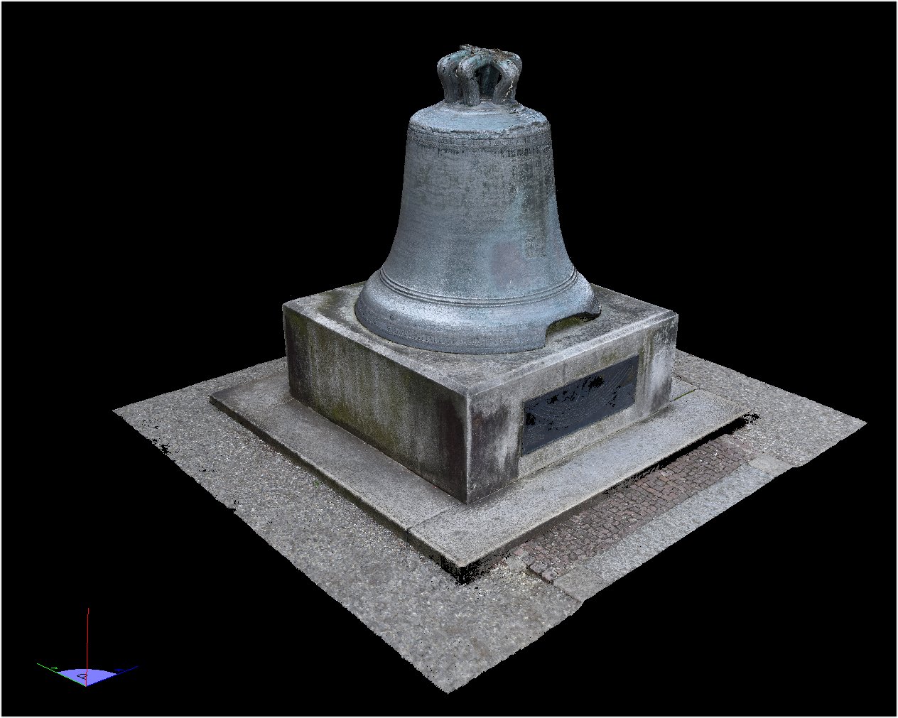
If you make another cut through the bell, you can easily judge the quality of the point cloud. Here a 20cm wide cut through the bell was made, you can see well how detailed and clean the point cloud is: