The plane to be defined in ELCOVISION 10 can be specified over any number of points; if a plane is created using more than 3 points, a balanced plane will be defined. Any number of spatial planes can be defined for each project. In contrast to the rectification planes, however, these planes cannot be limited
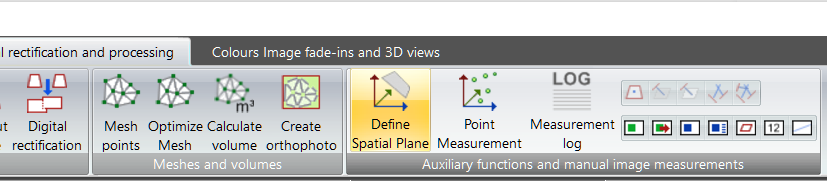
Define Spatial Planes
Here you can create planes that are arbitrarily positioned in space. If you are using the ELCOVISION 10 CAD plugin in a measuring mode, points can be clicked directly in the CAD graphic as plane definition points.
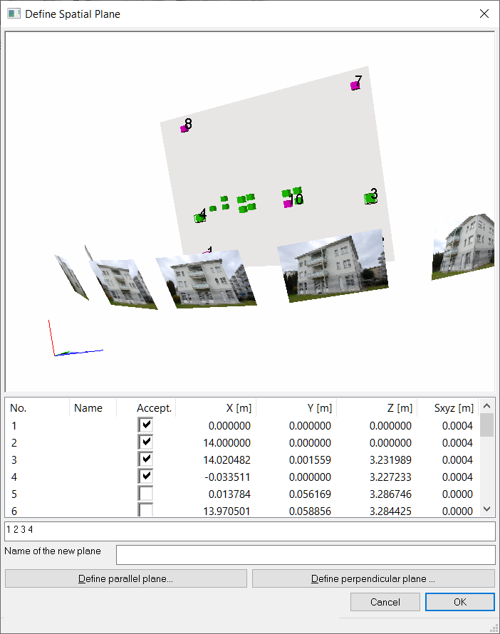
In the overview window or in the point list select the points that should define the plane. Use the deviation vectors and various views to check whether you have really defined the desired plane.
Point Cloud View
In the point cloud view, all object points and camera viewpoints are visible. The balanced plane through the selected points is displayed as a semi-transparent rectangular plane. If the selected points are not in a plane, blue cubes may also be visible. These mark the base points of the points used for plane definition in the plane.
Point List
Here all points and their deviations to the balanced plane are shown once again. The points defining the spatial plane are marked as accepted and are numbered and displayed in a different colour in the point cloud view.
Input field for point numbers
You can define a spatial plane by entering the point numbers manually. This can be helpful for huge point clouds if you don't want to "trudge" through the lists. All accepted points are also listed here for a quick check.
Name of the new plane
Enter a name here for a better overview. The plane number will be assigned automatically and consecutively by ELCOVISION 10.
Define parallel plane
Another dialog will be opened to create a plane parallel to any plane.
Define Perpendicular Plane
Opens another dialog to create a plane perpendicular to any plane by 2 points.
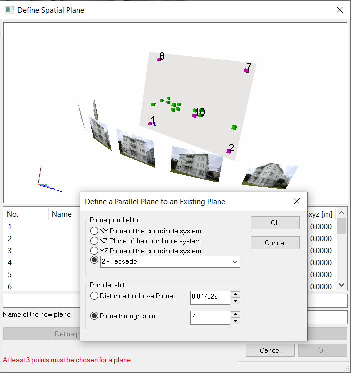
Definition of a Parallel plane
Plane parallel to
Select an existing plane from the list or define a plane parallel to the coordinate axes.
Distance to above Plane
This is the perpendicular distance to the selected plane. The direction depends on the definition of the plane. The coordinate system of the plane is an orthogonal right system. The plane is the XY plane of this system. If you are not sure whether the distance must be entered as positive or negative, check the parallel plane in the graphical representation in the Define Spatial Plane window after you have entered the parallel displacement. First define the parallel plane with clear (negative or positive) distance (1m or 2m), and compare it with the original plane. If the direction of the parallel plane is clear, define the actual parallel plane.
Plane trough point
You can also define a parallel plane by a point, select one here or click on it in the point cloud view in the previous dialog.
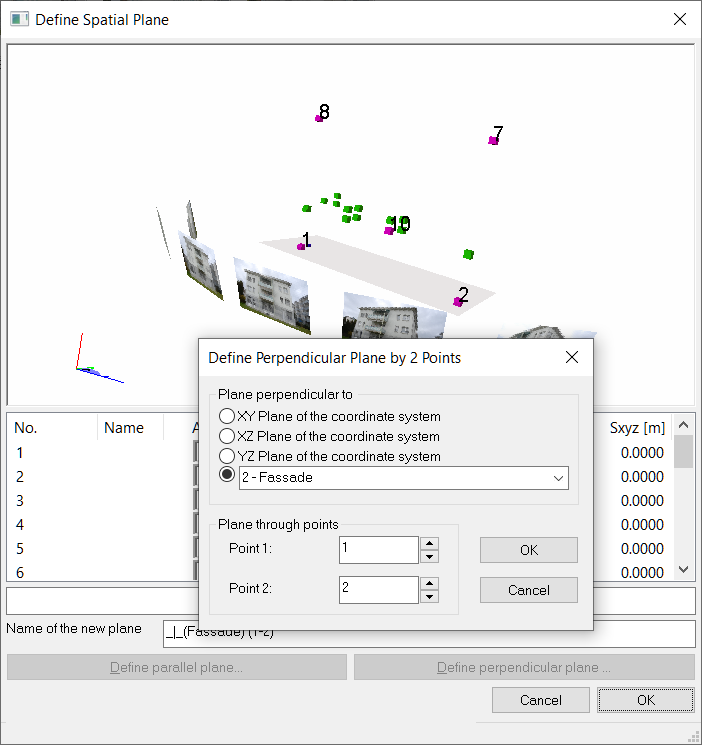
Definition of a Perpendicular Plane
Plane perpendicular to
Select an existing plane from the list, or define a plane perpendicular to the coordinate axes.
Plane through points
Select here the points through which the plane should pass. You can also click the points in the point cloud view or list in the "Define Spatial Plane" dialog.
This website uses cookies
Select which cookies to opt-in to via the checkboxes below; our website uses cookies to examine site traffic and user activity while on our site, for marketing, and to provide social media functionality. More details...
Cookie settings
We use cookies to enhance your browsing experience, serve personalized ads or content, and analyze our traffic. By clicking "Accept All", you consent to our use of cookies. More details...