
Quick Guide Drone Roof Survey
In this example drone images of a roof are evaluated.
Among other things, the following will be shown:
- Flight planning
- Recommended drone settings
- Import of the images
- Fully automatic image orientation
- Scaling and georeferencing of the photo block with drone GPS coordinates
- Definition of a local coordinate system
- Scaling the photo block by distances
- Generation of a high-density point cloud
- Export of the results
Example images and demo project
You can download the images and a finished project with high-density point cloud for this example here:
https://www.elcovision.com/ExamplesHD/Hausdach.zip
You can find more examples to calculate yourself here::
https://en.elcovision.com/elcovision-10-beispiele.html
Flight preparation and planning
The best weather for flying is when the sky is cloudy: there are then no harsh shadows and no over-illumination, the roof and the surroundings are softly illuminated and the image quality is much better.
The shutter speed of the camera should be as fast as possible so that there is no motion blur and no rolling shutter effect. The best way to achieve this is to set the ISO sensitivity > 400.
The flight altitude determines the accuracy of the result. As a rule of thumb you have 1-2cm height accuracy per 30m flying height, the position accuracy depends on the pixel size on the object and is typically 2-3 times higher with normal cameras. Depending on the camera, flight heights of 5-10m above the highest point of the roof are optimal for roof surveys.
The roof should be flown in a checkerboard fashion with 75% image overlap. This ensures that every point is visible in at least 5-6 pictures. If the roof has many protrusions such as chimneys, oriels etc., these cause visual shadows. Then it may be necessary to fly with even more image overlap.
If you do not have a drone with RTK GPS, you have to scale the image over at least 4 control points or at least 1 known route. Control points must be laid out before the flight and then measured with a theodolite or a GPS, 5m levelling staffs are excellent as reference distances.
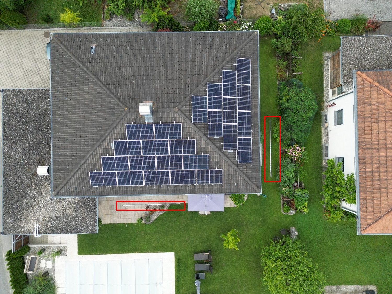
In this example, 2 5m levelling staffs were placed next to the house so that they were clearly visible:
The drone used here was a DJI Mini 3Pro with the following settings:
- Resolution: 48 MPixel = Maximum resolution
- Image format: 4:3 = Full sensor resolution.
- Sensitivity: ISO 800 = Fast shutter speeds.
- Camera focused to infinity.
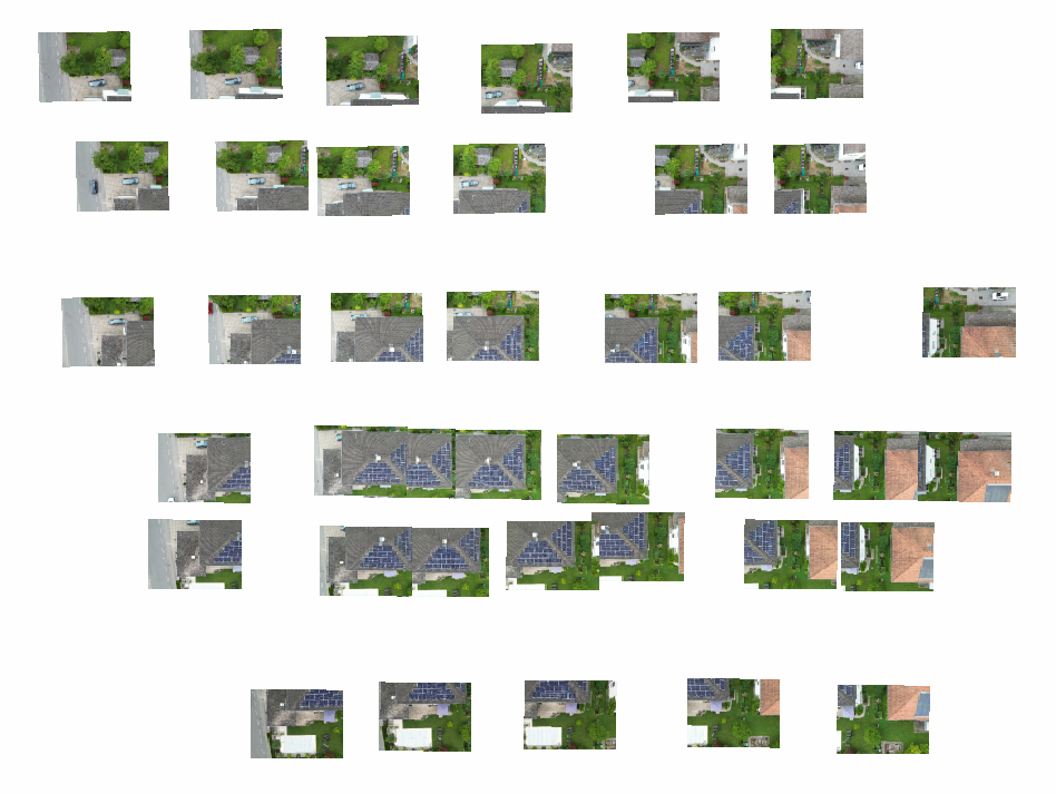
Flight altitude was approx. 18m above ground or approx. 12m above the roof, an attempt was made to photograph an uniform grid:
Ideally, the images should be saved to a local hard disk, preferably an SSD.
Launch ELCOVISION 10

Drag and Drop the Images into ELCOVISION 10
A new project will be created automatically and thumbnails of the images will be generated. The images are prepared for the automatic 3D reconstruction:
If you use your own images: If the ELCOVISION 10 camera is unknown, select a suitable CCD size from the dialogue "CCD size for unknown digital camera". This size should be close to the correct CCD size or ELCOVISION 10 may not be able to orientate the images correctly. It is best to send us such an image and we will add the CCD size to the CCD sizes file..
If the project window does not appear during loading, it is hidden somewhere in the background. At the top of the [Ribbon > Project Management and Orientation > Windows] select either Cascade Windows or Tile Windows.
Start the Automatic 3D Reconstruction
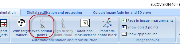
Start the automatic reconstruction using Automatic Orientation and Reconstructions - With Natural Points:
A "Save As" dialogue appears. Save the project if possible on a local hard disk, preferably an SSD with enough free space for the temporary data generated by ELCOVISION 10..
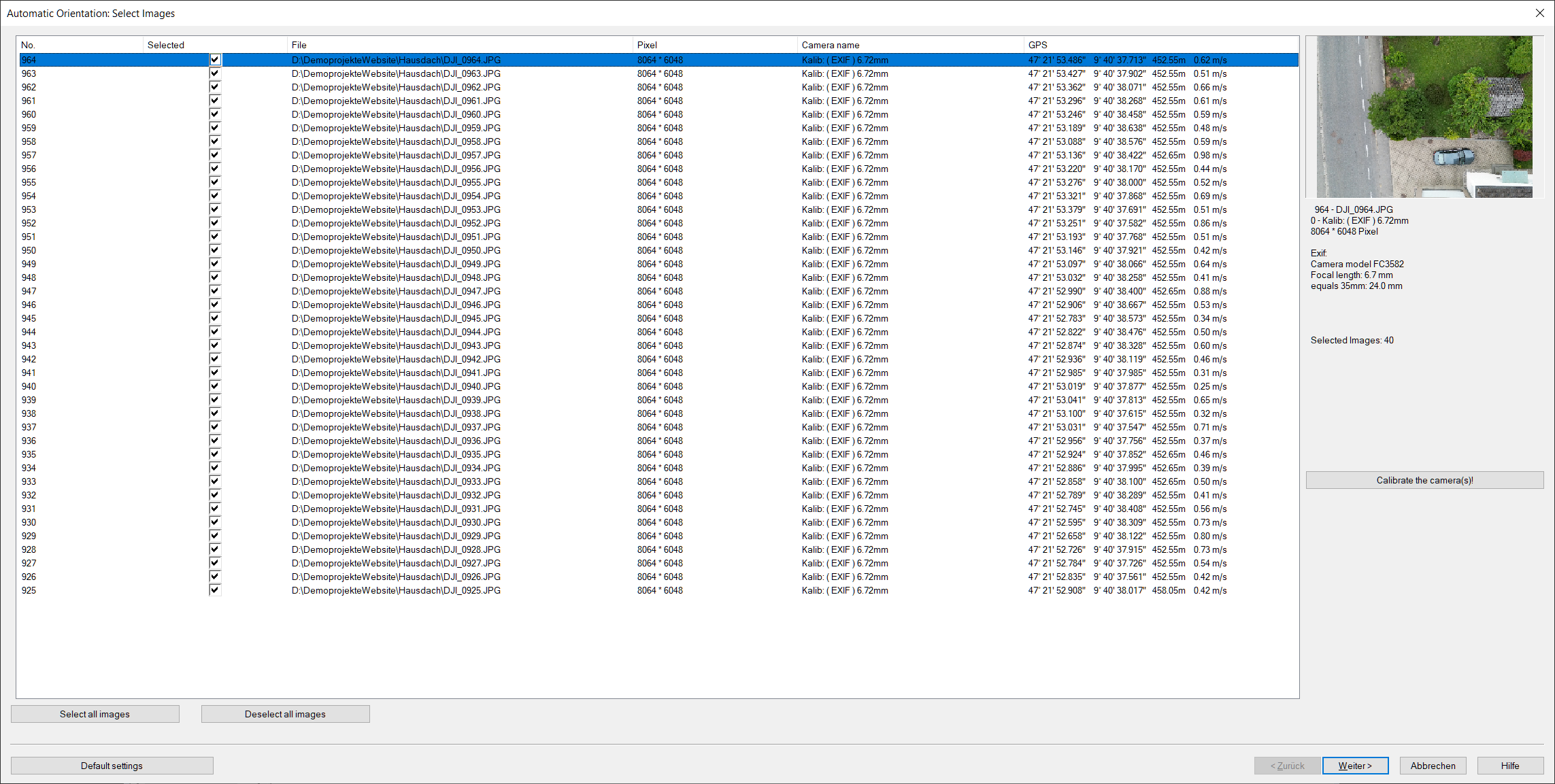
Then the first page of the Orientation Wizard appears::
Click Next >. The page for the camera calibration settings appears:
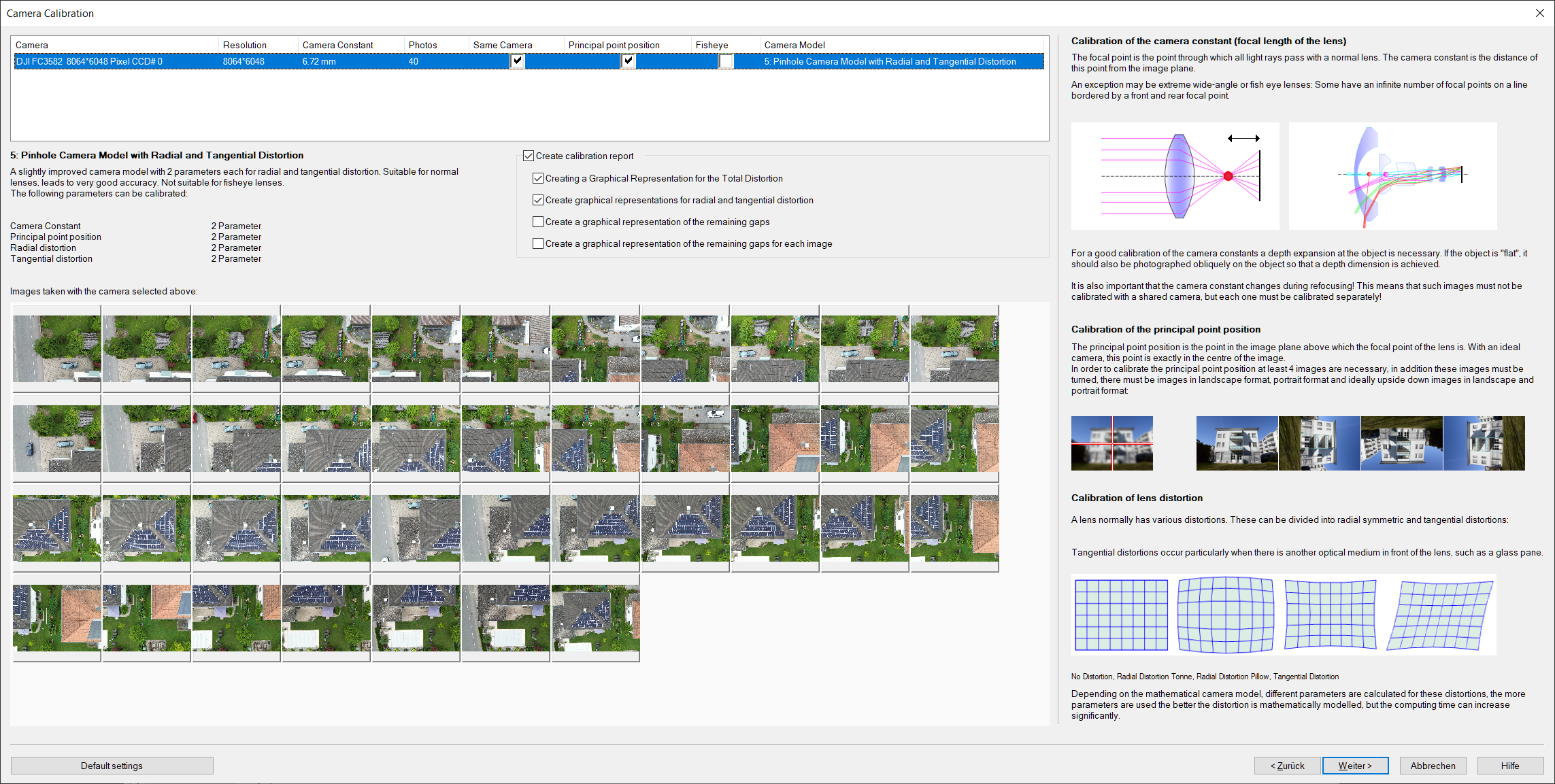
If you took pictures yourself and the camera was refocused during shooting, uncheck "Together" in the camera list.
Press Next >. The final configuration page for automatic orientation appears:
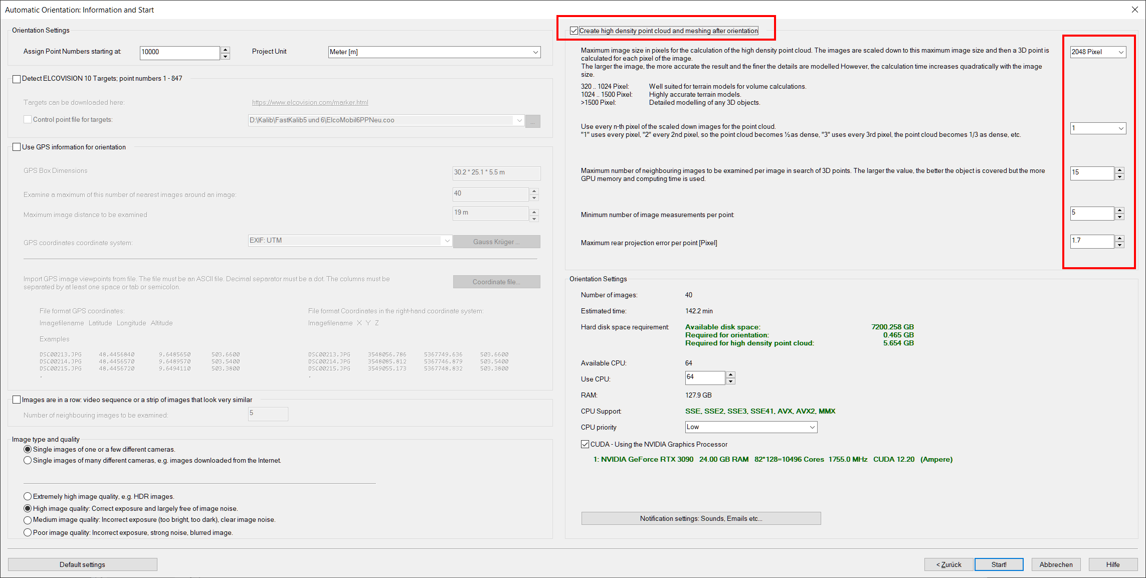
For this example we calculate a high density point cloud at the same time. Activate "High-density point cloud" and select approx. 2048 pixels as the maximum image size. This produces quite a good result and the calculation time is still within the range of a few minutes. Alternatively, you can also calculate the high-density point cloud later, in which case the calculation time is 1-2 minutes.
Press Start!.
ELCOVISION 10 starts the calculation and displays the calculation progress. After some time you will get the result:
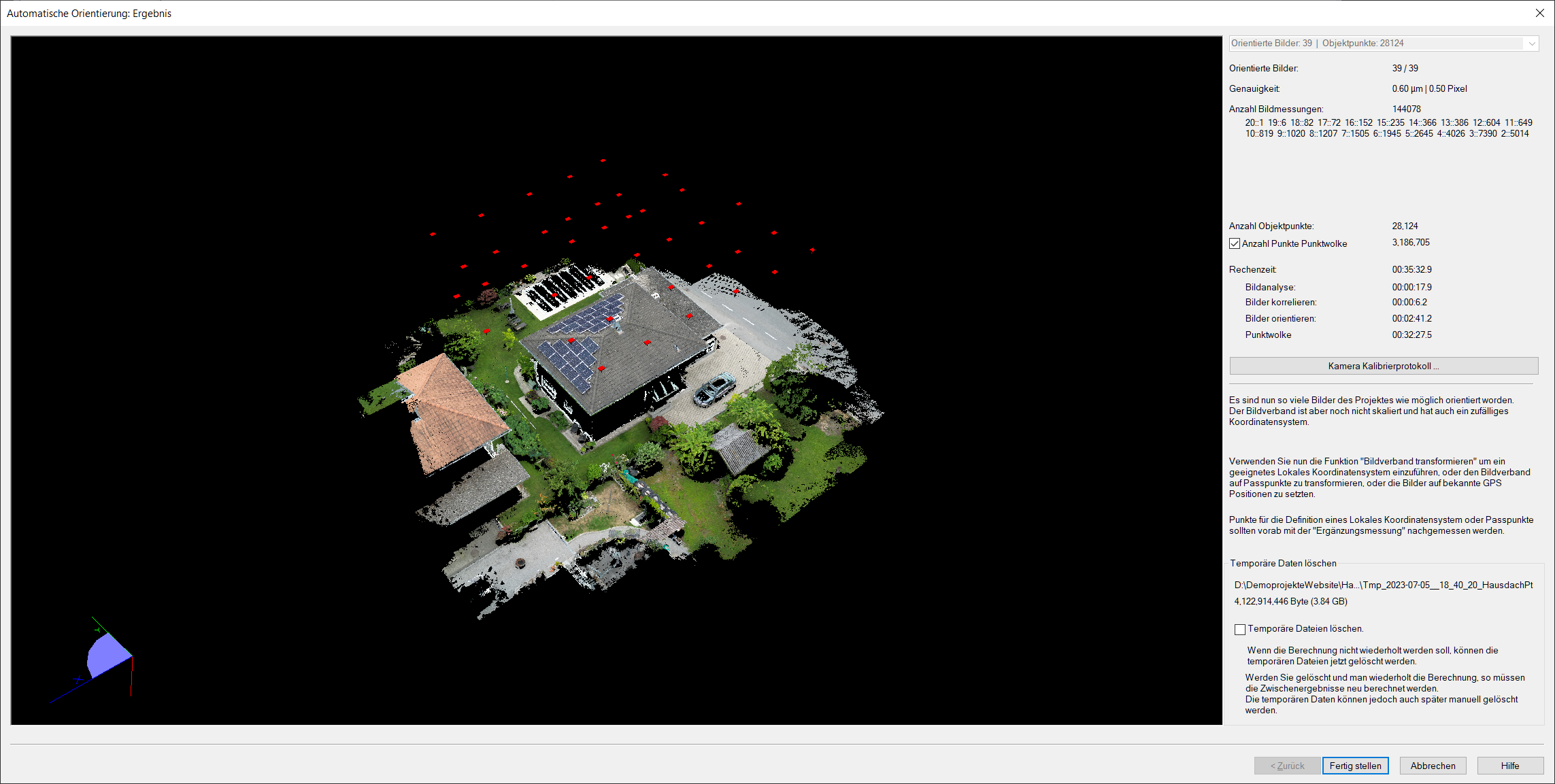
The photo block is now oriented, but the correct scale and the correct coordinate system are still missing. This can now be done by manually measuring points for a local coordinate system or for control points. If a drone with RTK-GPS was used, the photo block can be scaled and aligned directly with the GPS coordinates of the images:
Georeferencing and Scaling of the Photo Block with Image GPS Coordinates
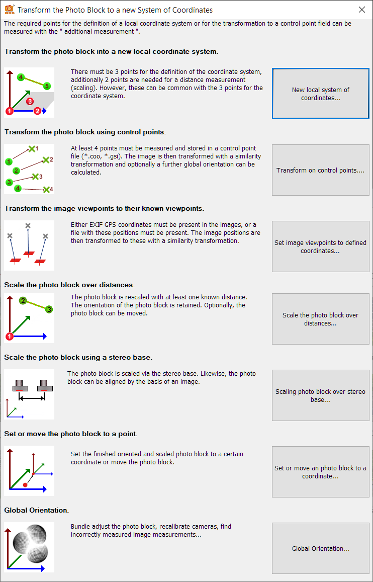
Start the function Transform photo block.
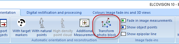
Select Set image viewpoints to defined coordinates
The following dialogue appears:
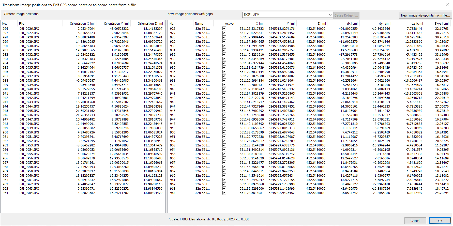
UTM, UTMREF and Gauss Krüger can be selected as coordinate systems.
If an RTK GPS drone would have been used, the photo block would now be correctly scaled and georeferenced, and the high-density point cloud could be immediately cropped and exported..
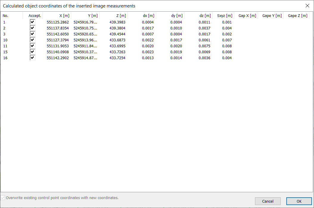
But since normal drones have very poor GPS accuracies, you have to scale the photo block with known distances. How bad the GPS coordinates are can be seen in the columns dx, dy, dz, and Sxyz in the dialogue above. Here we have deviations of 20-25cm on average. With RTK-GPS data, gaps of < 2cm are normal..
Definition of a Local Coordinate System and Manual Measurement of Reference Distances
Load the images in which you want to measure points by double-clicking on the thumbnails in the project manager. If the images are too large or too small, they can be made larger or smaller using the context menu. They can also be rotated to make them readable. Arrange the images clearly on the screen.
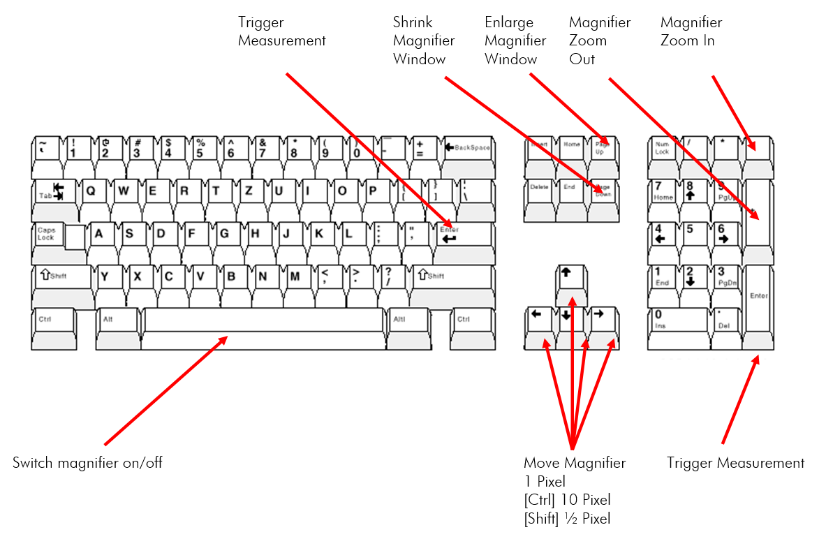
In digital images, the mouse pointer is used to measure. If the mouse is moved over a digital image, the mouse pointer is transformed into a measuring cursor, and a corresponding enlargement of the image section around the measuring cursor area is automatically visible in the digital magnifier. The measurement cursor can be controlled in different ways:
| Mouse Movement | The measuring cursor is moved accordingly. |
| Ctrl + Mouse movement | The measuring cursor is moved in 10 pixel steps in the in the magnifier window |
| Ctrl + Cursor keys | The measuring cursor is moved in 10 pixel steps |
| Shift + Mouse movement | The measuring cursor is moved in ½ pixel increments in the magnifier window |
| Shift + Cursor keys | The measuring cursor is moved in ½ pixel increments |
| Cursor keys | The measuring cursor is moved in 1 pixel increments |
| Mouse Wheel | Zoom in/out |
| Ctrl + Mouse Wheel | The magnifier window is enlarged or shrunk. |
| Enter Left Mouse Button | A measurement is triggered |
| Middle Mouse Button | The magnifier is switched on/off. Measurements can only be made when the magnifier is switched on! |
| Right Mouse Button | Context menu in which, among other things, the fixed/flowing magnifier can be selected. |
Overview of the key assignment
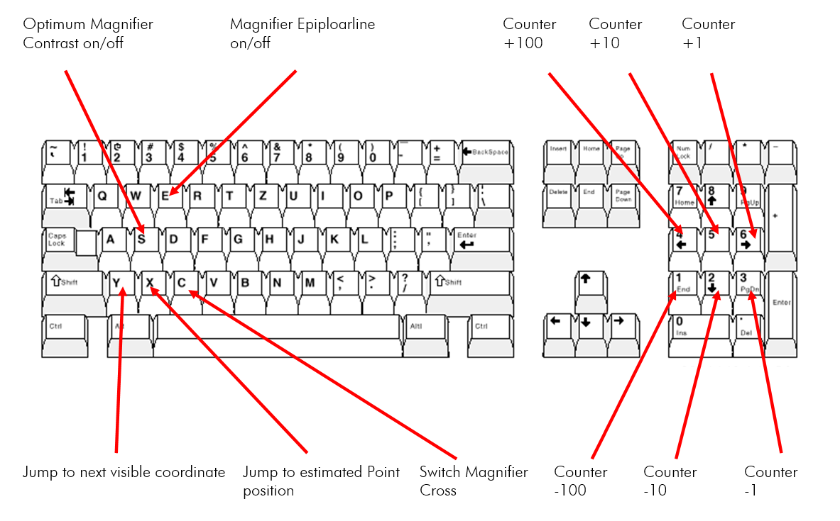
Recommended precedence when measuring points:
- Move the mouse approximately to the position of the point you want to measure.
- In case of the static magnifier: Let go of the mouse
- Use the cursor keys on the keyboard to fine-tune the point.
- Finish the measurement by pressing Enter. Do not use the left mouse button as this can easily affect the set measurement point.
Start additional measurements
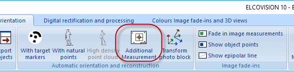
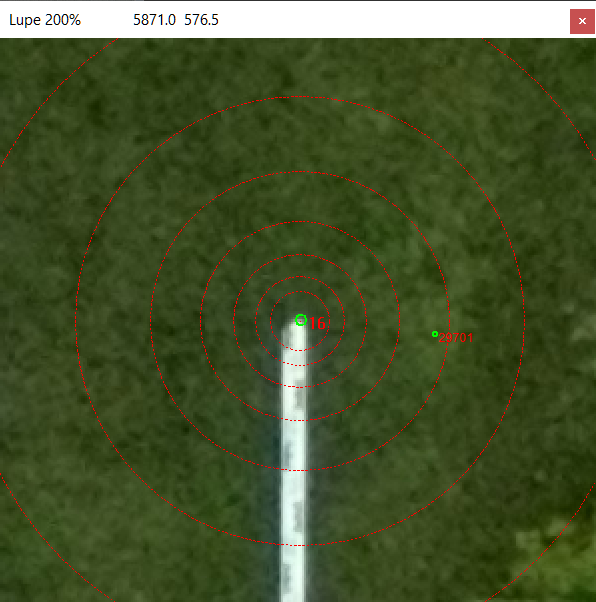
The following points are now measured with the additional measurement: 3 points on the rain gutter, 4 points on the 2 levelling staffs:
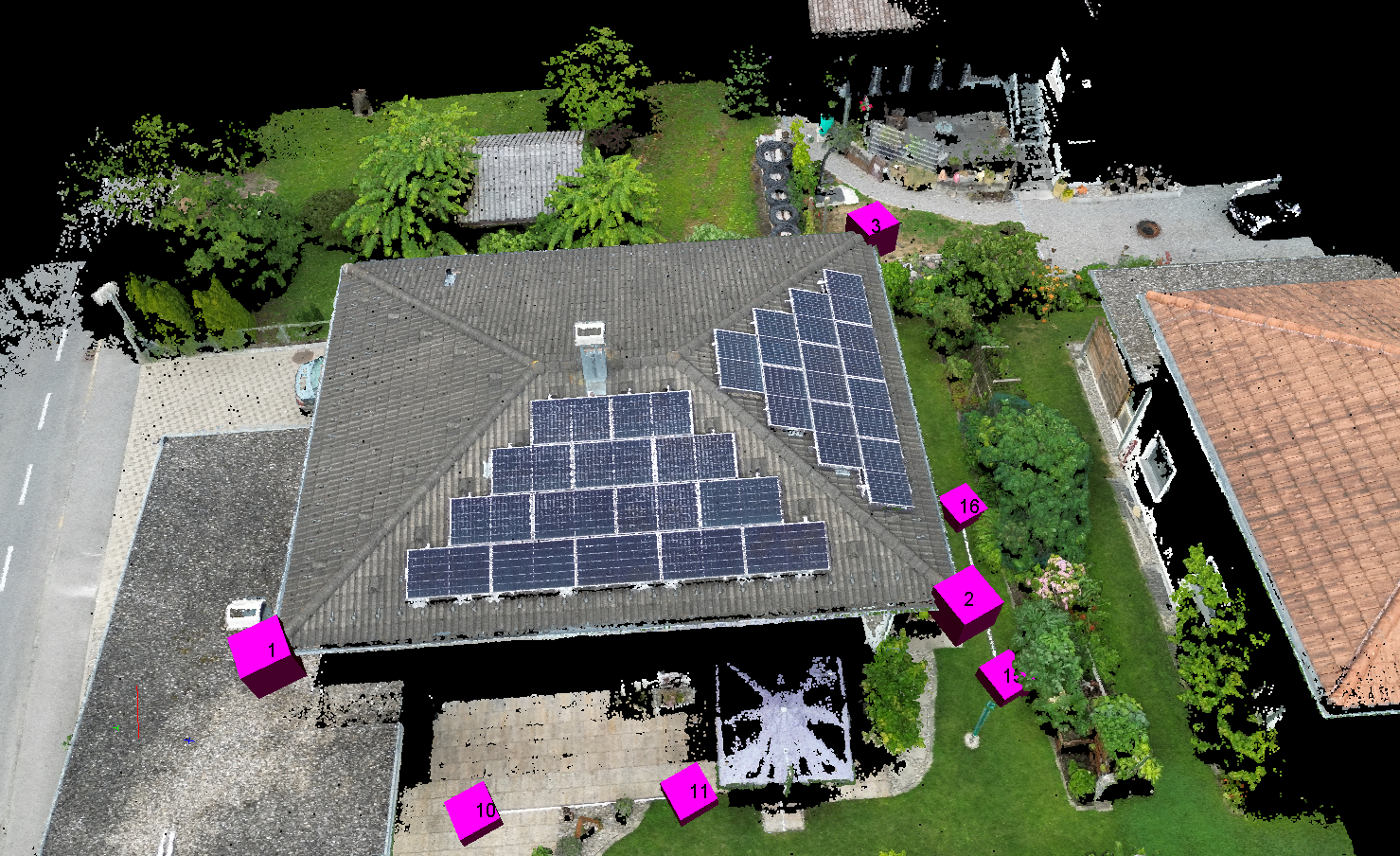
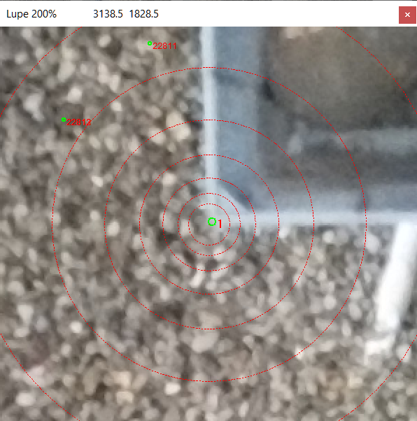
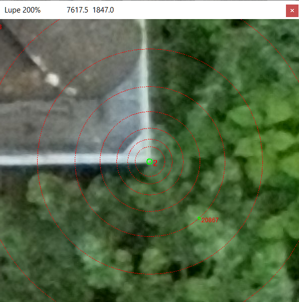
Points 1,2,3: Corner points on the rain gutter, these will later define the X axis and XY plane of the system of coordinates:
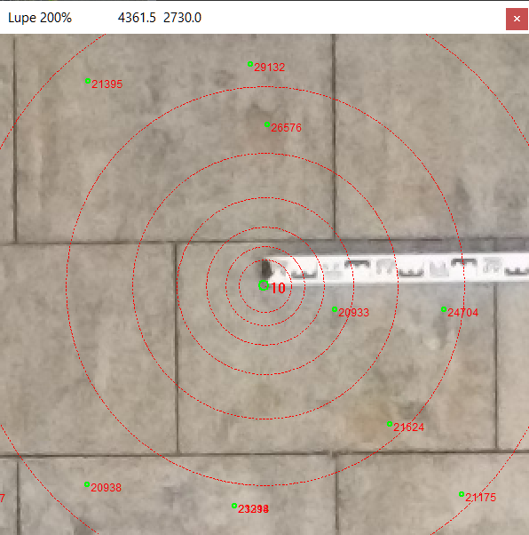
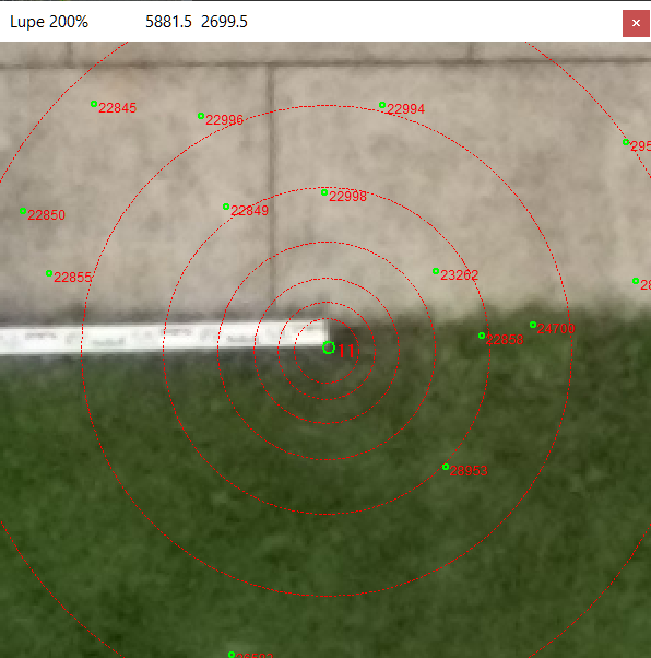
Points 10,11: Levelling staff on the terrace, reference distance #1:
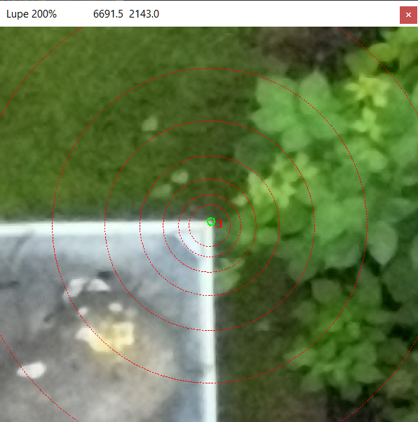
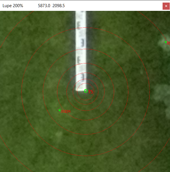
Points 15,16: Levelling staff on the lawn, reference distance #2:
Each point is measured in 3-4 images so that a good accuracy and overdetermination is achieved. Since the photo block has already been georeferenced with GPS data above, the accuracy specifications in the supplementary measurement window are reliable.
In the additional measurement you have to measure carefully, if a point is measured slightly wrong you should simply measure the point again. In points 1-3, accuracy in position (XY plane) should be better than 2mm, and in height better than 4mm.
Points 10,11,15,16 have slightly worse accuracies due to the greater distance to the images..
If you do not want to make all the image measurements yourself, drag the Hausdach.imo file contained in the zip file into the project window. These image measurements are then imported and a forward section is calculated and the object points are generated:
Definition of a Local System of Coordinates
Start the function Transform photo block.

The following dialogue box appears:
Click on the first entry, New local system of coordinates the following dialogue appears:
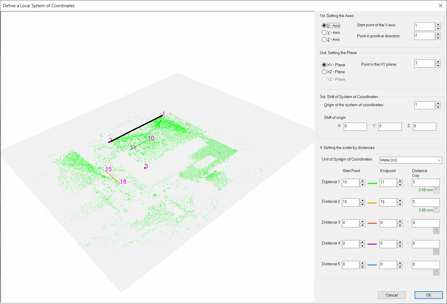
Enter the following data as shown above, most of the data for the orientation of the coordinate system should already have been entered automatically:
1. Setting the Axes
- Starting point of the X Axis: 1
- Point in positive Direction: 2
2. Setting the Plane
- Point in the XY plane : 3
The XY plane of the coordinate system is now placed on the rain gutter. For most applications, the object's horizon is accurate enough.
3. Shift of System of Coordinates
- Origin of System of Coordinates: 1
- Shift of origin: 0,0,0
4. Setting the scale by distances
- Distance 1: Start Point 10 - End Point 11, Distance 5m
- Distance 2: Start Point 15 - End Point 16, Distance 5m
Below the input fields of the distance the remaining gaps are shown in green or red. In this example the pixel size on the ground is approx. 3.5mm i.e. the measuring accuracy on the ground is approx. 3.5mm. The calculated line gap is approx. 3.5mm, which is well within the expected accuracy. The new coordinate system is adopted by OK.
The photo block and thus the point cloud are now correctly scaled and the desired coordinate system is now defined. You can now crop the point cloud if desired and then export it.
Scaling the Photo Block over Distances
This method can be used if the alignment of the photo block is to be maintained or if a local coordinate system cannot be easily created. It can be particularly advantageous when using drones without RTK GPS.
In this case, only the end points of the distance need to be measured with the additional measurement:
Points 10,11: Levelling staff on the terrace, reference distance #1:
Points 15,16: Levelling staff on the lawn, reference distance #2:
Each point is measured in 3-4 images so that a good accuracy and overdetermination is achieved. Since the photo block has already been georeferenced with GPS data above, the accuracy specifications in the supplementary measurement window are reliable.
Start the function Transform photo block.
The following dialogue box appears:
Click on the first entry, Scale the photo block over distances the following dialogue appears:
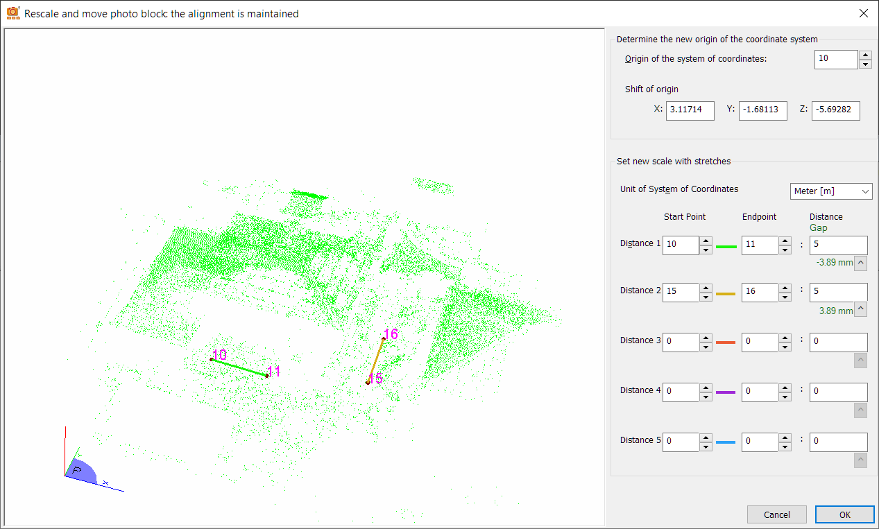
Enter the following data as shown above, most of the data for the orientation of the coordinate system should already have been entered automatically:
1. Set new origin of coordinate system
- Origin of System of Coordinates: 10
- Shift of origin: 0,0,0
2. Setting the scale by distances
- Distance 1: Start Point 10 - End Point 11, Distance 5m
- Distance 2: Start Point 15 - End Point 16, Distance 5m
Below the input fields of the distance the remaining gaps are shown in green or red. In this example the pixel size on the ground is approx. 3.5mm i.e. the measuring accuracy on the ground is approx. 3.5mm. The calculated line gap is approx. 3.5mm, which is well within the expected accuracy. The new coordinate system is adopted by OK.
The photo block and thus also the point cloud are now correctly scaled, but the alignment remains the same. You can now crop the point cloud if desired and then export it.
Trimming the Point Cloud
Select View "Point clouds" in the project window and rotate the view so that it shows the point cloud from above. If the X axis of the coordinate system is oriented along the gutter as shown here, the view from above can be set via the context menu > Set View > XY Plane or by pressing 1 in the 3D view.
Select the point cloud of the house:
| Shift ⇧ + Left Mouse Button | Start selection, the mouse cursor changes to the selection cursor |
| Draw rectangle | Move mouse |
Release | The points enclosed by the rectangle are selected and displayed in magenta |
| Esc | The selection is cleared |
| * | The selection is inverted |
The point cloud can now be trimmed via the context menu or with Strg + Del:
Export the Point Cloud
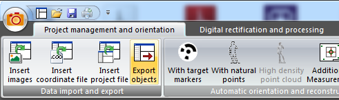
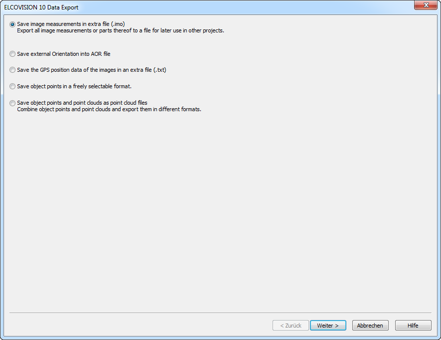
Click on Data Import and Export - Export Objects
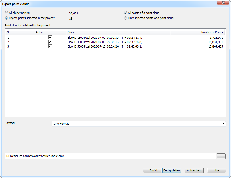
The export dialogue appears. Select Save object points and point clouds as point cloud files and click on Next >, activate the point clouds you want to export and select the desired export format:
Read also the other quick guides. There you will find further evaluation options..